Elgar - 501 Series - Power supply
Manufacturer:
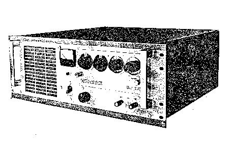
Image 1 of 1
If you have any other photos or manuals for the
Elgar 501 Series
you can
upload the files here.
Equipment:
501 Series
Date:
Category:
Group:
Sub Group:
Information
The Series 500 Power Sources provide AC power at precise
frequencies for testing, motor operation, and frequency
conversion. The basic power amplifier consists »of two DC
supplies and a 4-stage, transformer-coupled amplifier with
an adjustable power output transformer. The output
transformer provides nominal output voltages of 28, 115, and
230 VAC. Total available power is 500 volt-amperesat
full-rated outputs of 28, 115, or 230 VAC. Power at less
than füll voltages is derated as illustrated in Figure 1-1.
Input power is 115 or 230 VAC at 50 or 60 Hz. Units
operating with 400 Hz input power are available on special
order.
Output power frequency is established by a plug-in
oscillator. Output frequency range is 45 to 10,000 Hz. The
output is derated to half power at frequencies above 5 KHz.
A variety of plug-in oscillators are available, with
frequency accuracy up to 0.0001%.
The Elgar Power Source facilitates equipment tests to meet
military-specification operating requirements over the
frequency range of 47 to 63 Hz or 47 to 425 Hz. The basic
power amplifier output is single phase, but multiphase power
output can be obtained by stacking two or three power
amplifiers, all driven by thesame plug-in oscillator.
GENERAL DESCRIPTION
The Series 500 Power Source is contained in a rack- mount
enclosure with a meter for power output monitoring,
130 110 90 70 50 30 10 0 OUTPUT VOLTAGE (RM$f
FIGURE 1-1. POWER OUTPUT DERATING VS OUTPUT VOLTAGE
a POWER ON indicator lamp, an output voltage AMPLl-
TUDEcontrolandaPOWERswitch-circuit breaker located on the
front panel. Cooling air is drawn through a front panel
grill and exhausted at the rear of the enclosure.
The enclosure contains two heatsinks which comprise a power
amplifier. Control circuitry is mounted on a circuit board
with test points and adjustment controls available at the
top of the board. Output power is available atarear panel
terminal strip and at front panel connectors. An input power
cord is located on the rear panel.
1 Manual
Service and user manual
Manual type:
Service and user manual
Pages:
17
Size:
1.1 MB
Language:
english
Revision:
Manual-ID:
Date:
Quality:
Scanned document, reading partly badly, partly not readable.
Upload date:
May 29, 2016
MD5:
b3d5ec50-f2f6-1b1c-65aa-0fe26bef68d9
Downloads:
474