Conar Coletronics Service Inc. - 224 - Valve characteristic meter
Manufacturer:
No picture available!
Maybe you can
upload a pic
for the
Conar Coletronics Service Inc. 224 ?
If you have any other manuals for the
Conar Coletronics Service Inc. 224
you can
upload the files here.
.
Equipment:
224
Date:
1972
Category:
Group:
Sub Group:
Information
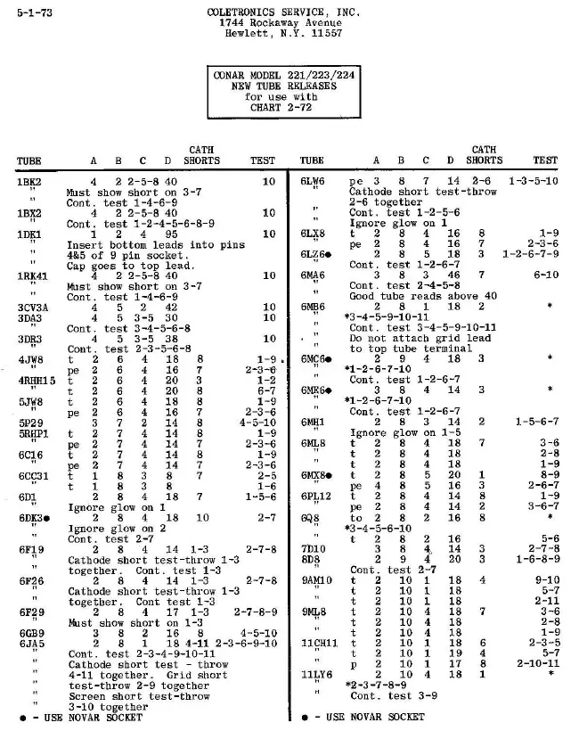
The heart of the Model 224 is the 12-lever switch. With This
switch, any tube pin can be connected to any of three
circuits. The individual switches, numbered 1 through 12,
correspond to the twelve possible tube pins. That is, switch
1 connects to pin 1 of all sockets, switch 2 connects to pin
2 of all sockets, and so on. Switch 10 connects to pin 10 of
all sockets as well as to the top cap connector.
Note that all sockets do not require all twelve switches, in
fact, the compactron socket is the only one having 12 pins,
thus requiring all 12 switches. The other sockets will use
the first 6, 7, it, 9 or 10 switches, The five pins of the
nuvistor sockets, however, do not connect to switches 1
through 5, The tube manufacturers have chosen to call these
five pins 2,4, 8, 10 and 12, so this socket uses switches 2,
4,8, 10 and 12.
When any of the twelve switches is in the TEST (middle)
position, an ac voltage is applied to the corresponding tube
pin through the neon lamp. If there is a conductive path of
1 megohm or less between the selected tube electrode and any
other electrode, the neon lamp will glow. In this way
inter-element shorts and undesirable leakage between
electrodes may be discovered. This same circuit can be used
to check heater continuity, in which case the lamp should
glow if the tube heater is good.
When the switch corresponding to the tube heater is placed
in the C position (upper), heater voltage is applied to the
tube by the B selector switch. Any of 17 separate heater
voltages may be chosen by the B switch (position 18 is not
used). With the proper switch set to C, the tube healer will
light. All other tube elements except the cathode and the
other heater connections are placed in the TEST position by
setting the appropriate switches. This connects the tube as
a diode. When the Press-To-Read-Meter switch is pushed, the
neon lamp is disconnected and a voltage and load resistor
combination selected by the A switch is connected instead.
At the same time, the meter is disconnected from the Adjust
Line circuit and reconnected to read the tube current. The
current can be read either on the 0 to 100 scale or the
REPLACE — ? — GOOD scale.
5 Manuals
User manual
Manual type:
User manual
Pages:
25
Size:
719.8 KB
Language:
english
Revision:
Manual-ID:
Date:
Quality:
Scanned document, reading partly badly, partly not readable.
Upload date:
Aug. 5, 2017
MD5:
17e3e01b-877c-fb63-3b22-8c646f734843
Downloads:
841
User manual
Manual type:
User manual
Pages:
3
Size:
1018.5 KB
Language:
english
Revision:
Manual-ID:
Date:
January 1973
Quality:
Scanned document, reading partly badly, partly not readable.
Upload date:
Aug. 5, 2017
MD5:
81c82b20-f215-8b06-07df-6d286cbb87ed
Downloads:
891
User manual
Manual type:
User manual
Pages:
30
Size:
9.7 MB
Language:
english
Revision:
Manual-ID:
Date:
January 1972
Quality:
Scanned document, reading partly badly, partly not readable.
Upload date:
Aug. 5, 2017
MD5:
9d78aeb0-2e4b-4d14-6a42-ece0131bfa4e
Downloads:
373
User manual
Manual type:
User manual
Pages:
40
Size:
652.0 KB
Language:
english
Revision:
Manual-ID:
Date:
January 1978
Quality:
Scanned document, reading partly badly, partly not readable.
Upload date:
Aug. 6, 2017
MD5:
6f8ed0a7-f0b4-397e-98d0-0fed9e470101
Downloads:
480
User manual
Manual type:
User manual
Pages:
16
Size:
282.0 KB
Language:
english
Revision:
Manual-ID:
Date:
Quality:
Scanned document, reading partly badly, partly not readable.
Upload date:
Aug. 6, 2017
MD5:
06111eae-c3ad-0212-b240-040eec86d81b
Downloads:
590