Associated Research Incorporated - 4045AI - Level Meter
Manufacturer:
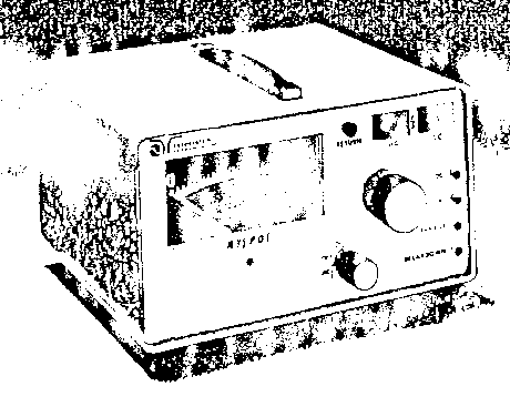
Image 1 of 1
If you have any other photos or manuals for the
Associated Research Incorporated 4045AI
you can
upload the files here.
Equipment:
4045AI
Date:
1987
Category:
Group:
Sub Group:
Information
1. Wide, easily read 4-1/2 inch AC/DC kilovoltmeter with 2%
of full scale accuracy.
2. Detachable 5 foot return (ground) lead. This lead is
always used in performing tests and is grounded for safety.
3. Detachable 5 foot high voltage lead with flexible rubber
insulation for easy handling. Control panel Jacks are well
recessed for safety.
4. Lighted AC and DC indicators on the control panel which
show that the High Voltage circuit Is enabled ("Power 0a")
and Indicate which node
of operation was selected by rotating the power switch to
either the AC or DC position*
5. Lighted Breakdown and Leakage Indication. If excessive
current is drawn during the Hypot* test, the yellow leakage
indicator will illuminate and an audio alarm will sound.
Should any arcing occur during the Hypot* test, both the
yellow leakage indicator and the orange breakdown indicators
will illuminate. To reset the unit, simply decrease the
output voltage to zero, place the power switch Into the
"Off" position and remove whatever is causing the failure
from the output leads.
6. Voltage adjust knob. This control varies the High voltage
from near zero to the full 5000 volts AC or 5000 volts DC.
The voltage can be adjusted only when the high voltage
circuit is energised. It is recommended that the voltage
control be returned to zero at the end of each test.
7. Detachable 7-1/2 fooc power cord with standard coanector.
8. Line fuse accessible from the rear. "Shock, safe" fuseholder.
9. Separate AC and DC Current Trip (sensitivity)
adjustments^ The current at which the Failure alarm will
trip is adjustable from approximately .3 mA to 5 mA AC or 3
mA DC. Turn the controls counterclockwise to decrease the
current setting and increase sensitivity.
Turn them clockwise to increase the current setting and
decrease sensitivity.
1 Manual
User manual
Manual type:
User manual

Pages:
13
Size:
825.9 KB
Language:
english
Revision:
Manual-ID:
Date:
January 1987
Quality:
Scanned document, reading partly badly, partly not readable.
Upload date:
Oct. 21, 2017
MD5:
987e1ad9-da1a-1899-6ea0-3dea1203041d
Downloads:
298