Hickok Electrical Instrument Company - 512 - Oscilloscope
Manufacturer:
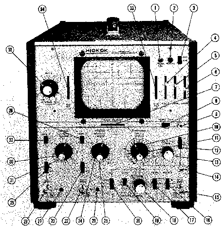
Image 1 of 2
If you have any other photos or manuals for the
Hickok Electrical Instrument Company 512
you can
upload the files here.
Equipment:
512
Date:
Category:
Group:
Sub Group:
Information
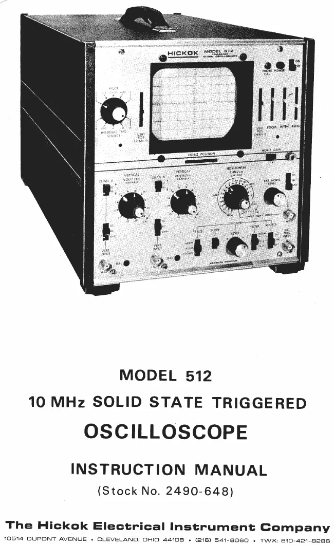
1-1 DESCRIPTION
The Hickok Oscilloscope covered by this instruction manual has been especially designed to fulfill the need for a highly stable, triggered sweep, solid state oscilloscope for general purpose industrial use. Due to many unique features, it is also ideally suited for use by television, audio and radio service technicians.
Special features of this instrument which are essential for testing and servicing modern electronic equipment are:
a. The vertical system has dual channel amplifiers which allows two waveforms to be displayed simultaneously to compare their time or phase relationship. The two channels can be displayed separately, simultaneously or added together algebraically.
b. Each of the two vertical channels includes a step attenuator, to provide calibrated input voltage ranges, and a variable gain control, to permit adjustment between steps or ranges. Vertical input may be either AC or DC coupled. Special circuitry provides minimal overshoot, ringing and drift in the amplifier.
c. The horizontal amplifier system provides for either AC or DC coupled inputs and includes a variable gain control. The XI - X5 gain switch permits expanding the display for easy viewing.
d. A digital type trigger circuit, offers very stable triggering with minimum jitter to 15MHz without the use of high frequency sync adjustments. This permits the oscilloscope to be used to full bandwidth.
e. Calibrated sweep speeds in 18 steps with continuous adjustment between steps.
f. Special circuitry and control settings for viewing TV horizontal lines, vertical frames and vertical interval test signals (VITS) field 1 or field 2.
g. Overload protection on all ranges to protect the equipment from accidental application of excessive input voltage.
h. Regulated power supply for increased stability and accuracy.
i. Z axis blanking is provided by a Z Axis Input connector located on the back panel of the oscilloscope.
j. A trace locator circuit actuated by a momentary push switch permits rapid location of off-screen traces which may then be centered on the screen by the positioning controls,
1 Manual
Service and user manual
Manual type:
Service and user manual
Pages:
72
Size:
6.3 MB
Language:
english
Revision:
Manual-ID:
2490-648
Date:
Quality:
Scanned document, all readable.
Upload date:
Jan. 7, 2013
MD5:
8786d8d8-09f4-1371-e301-13b4c613fcaf
Downloads:
639