Grundig - XERIA GV 5053 HiFi - Videorecorder
Hersteller:
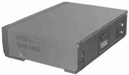
Bild 1 von 5
Weitere Anleitungen und Fotos für ein
Grundig XERIA GV 5053 HiFi
können sie
hier hochladen.
Gerät:
XERIA GV 5053 HiFi
Datum:
2000
Kategorie:
Gruppe:
Untergruppe:
Informationen
1 Handbuch
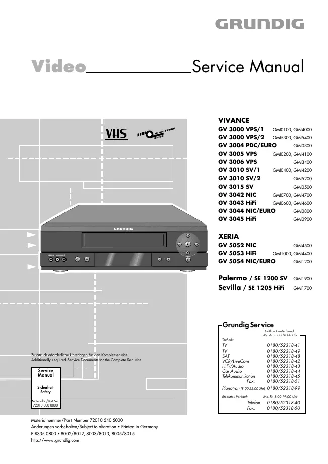
Reparaturanleitung
Dokumenttyp:
Reparaturanleitung
Seitenanzahl:
128
Größe:
14,2 MB
Sprache:
Englisch, Deutsch
Revision:
first edition
Dokument-ID:
72010 540 5000
Datum:
Qualität:
Elektronisches Dokument, kein Scan, sehr gut lesbar.
Upload Datum:
25. März 2012
MD5:
8f383b28-5db1-648c-f02c-d3ebcc398cc1
Downloads:
37712