Hewlett Packard - 620B - Generator
Hersteller:
Gerät:
620B
Datum:
1980
Kategorie:
Gruppe:
Untergruppe:
Informationen
DESCRIPTION.
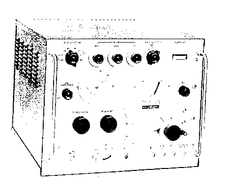
1-2. The Hewlett-Packard Models 618C/620B SHF Signal
Generators (Figure 1-1) provide RF signal output in the
frequency ranges of 3800 to 7600 MHz, and 7000 to 11,000 MHz
respectively. At least 1-mW power output is available over
the entire frequency range. The output frequency is
indicated on a direct-reading dial. The RF output power is
adjustable by an attenuator that is calibrated in µV and dB.
1-3. Five types of modulation are available: internal pulse
modulation, external pulse modulation, internal frequency
modulation, external frequency modulation, and internal
square-wave modulation.
1-4. The internal pulse modulation has a variable repetition
rate of 40 to 4, 000 Hz. Pulse width is variable from 0. 5
to 10 us as measured at the pulse 50% amplitude points.
Internal square wave modulation is variable from 40 to
4,000 Hz.
1-5. The Signal Generator can be modulated by external
pulses of positive or negative polarity. The amplitude of
the modulating pulses may be 20 to 70V, and the pulse width
between 0.5 and 2500 µs.
1-6. Internal frequency modulation comprises a sawtooth
sweep rate of 40 to 4,000 Hz. Frequency deviation is
variable from 0 to 5 MHz over most of the band. External
frequency modulation from an external sine wave is provided.
Frequency deviation is approximately 5 MHz.
1-7. Synchronization outputs of the Signal Generator
comprise two types: delayed, and undelayed. The delayed
synchronization output is a positive pulse that
occurs simultaneous with the RF pulse. The pulse has an
amplitude of 25 V minimum and a rise time less than 1 µs
when terminated in a load of 1000 ohms or more. The
undelayed synchronization pulse has the same characteristics
as the delayed pulse, except the pulse occurs between 3 to
300 µs (as adjusted by front-panel control) before the RF pulse.
1-8. Both the pulse- and frequency-modulated RF output may
be synchronized with the following externally generated
signals: sine waves of 40 to 4, 000 Hz, and 5 to 50V
amplitude; pulses of 40 to 4,000 Hz, a peak amplitude of 5
to 50V, a rise time of 0.1 to 1 µs, and a width of 0.5 to 5 µs.
1 Handbuch
Reparatur und Bedienungsanleitung
Dokumenttyp:
Reparatur und Bedienungsanleitung
Seitenanzahl:
138
Größe:
6,1 MB
Sprache:
englisch
Revision:
Dokument-ID:
00618-90029
Datum:
April 1980
Qualität:
Gescanntes Dokument, alles ist lesbar.
Upload Datum:
30. Dezember 2017
MD5:
d2021163-62c9-20aa-9e87-e1cc80581ed3
Downloads:
855
Informationen
I GENERAL INFORMATION......................1-1
1-1. Description..............................1-1
1-9. Instrument Identification............1-1
II INSTALLATION....................................2-1
2-1. Incoming Inspection..................2-1
2-3. Preparation for Use..................2-1
2-4. Power Requirements............2-1
2-6. 115/230 Volt Operation..............2-1
2-9. Power Cable........................2-1
2-12. Cooling..............................2-1
2-14. Air Filter............................2-1
2-16. Repacking for Shipment..............2-1
in OPERATION........................................3-1
3-1. Introduction............................3-1
3-3. General Operating Information . . 3-1
3-7. Controls. Connectors and
Indicators............................3-1
3-9. Basic Operating Procedures ... 3-1
3-10. Turn On..............................3-1
3-11. Detailed Operating
Procedures......................3-1
3-13. Operation with the Dymec
DY-2650A Oscillator
Synchronizer....................3-1
IV PRINCIPLES OF OPERATION................4-1
4-1. Introduction............................4-1
4-3. The Modulator Section..............4-1
4-41. The RF Oscillator....................4-9
4-87. The Power Monitor.........4-14
4-91. The Power Supplies.........4-15
4-92. General Operating
Principles............4-15
4-96. -300 Volt Supply.........4-16
4-98. -1000 Volt Supply.........4-16
4-100. -1550 Volt Supply.........4-16
V MAINTENANCE....................................5-1
5-1. Introduction............................5-1
5-3. Maintenance Precautions. ... 5-1
5-4. Periodic Inspection..................5-1
5-5. Cleaning..............................5-1
5-7. Lubrication..........................5-1
5-9. Performance Tests..................5-1
5-10. Purpose..............................5-1
5-12. Test Equipment Required . . . 5-1 5-14. RF Power-Output
Accuracy Check................5-1
5-15. Frequency Accuracy.
Stability, and aFM
Check..........................5-1
5-16. Uncalibrated RF Output
Check..............................5-2
5-17. Internal Pulse-Modulation
Check..............................5-2
Section Page
5-18. Internal Square-Wave
Modulation Check...... 5-2
5-19. External Pulse Check..... 5-3
5-20. Internal FM Check....... 5-4
5-21. External FM Check...... 5-4
5-22. External Sine-Wave
Synchronization Check . . . 5-4 5-23. External Pulse
Synchronization Check . . . 5-4
5-24. Adjustments............. 5-5
5-25. Test Equipment Required . . 5-5
5-27. Power-Supply Voltage
Adjustments.......... 5-5
5-29. Adjustments Following
Replacement of Klystron
V114 (618C)............ 5-6
5-31. Adjustments Following
Replacement of Klystron
V114 (620B)............ 5-7
5-33. Calibrating the Frequency
Dial (618C).......... 5-9
5-35. Calibrating the Frequency
Dial (620B).......... 5-10
5-37. Calibrating the Pulse
Rate Control......... 5-11
5-39. Calibrating the Pulse
Delay Control......... 5-11
5-41. Calibrating the Pulse
Width Control......... 5-11
5-43. Power Set Meter
Adjustments.......... 5-12
5-46. Troubleshooting........... 5-12
5-47. Test Equipment Required . . 5-12
5-49. Isolating a Trouble to a
Circuit Section........ 5-12
5-66. Isolating Trouble in
Transistor Circuits....... 5-14
5-68. In-Circuit Testing....... 5-14
5-71. Testing Transistor s with
an Ohmmeter......... 5-14
5-73. Klystron Removal (618C)..... 5-14
5-75. Klystron Replacement (618C) . . 5-16
5-77. Klystron Removal (620B) .... 5-17
5-79. Klystron Replacement (620B) . . 5-17
5-80. Replacing Repeller Tracking
Potentiometer.......... 5-18
5-82. Replacing and Recalibrating
the Alternator (618C)...... 5-19
5-85. Replacing the Attenuator
Probe (618C)......... 5-19
5-87. Recalibrating the
Attenuator........... 5-19
5-88. Replacing and Recalibrating
the Attenuator (620B)...... 5-20
5-90. Replacing the Attenuator
Probe (620B)......... 5-20
5-92. Recalibrating the
Attenuator (620B)...... 5-21
5-94. Tube and Semiconductor
Replacement............5-21
5-96. Etched Circuits............5-21
5-98. Component Replacement .... 5-22
5-101. Transistor and
Semiconductor Diode
Replacement..........5-23
5-102. Q601. Q602 Lead Identification. . 5-23
VI REPLACEABLE PARTS............ 6-1
6-1. Information............... 6-1
6-3. Ordering Information........ 6-1
APPENDIX I SHF SIGNAL GENERATOR ..
1-1 APPENDIX II MANUAL CHANGES ......11-1