Hewlett Packard - Pavilion dv8000 - Notebook
Hersteller:
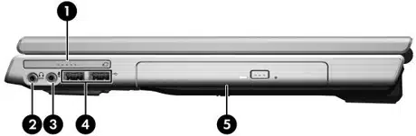
Bild 1 von 5
Weitere Anleitungen und Fotos für ein
Hewlett Packard Pavilion dv8000
können sie
hier hochladen.
Gerät:
Pavilion dv8000
Datum:
2006
Kategorie:
Gruppe:
Untergruppe:
Informationen
The HP Pavilion dv8200 Notebook PC and HP Pavilion dv8000
Notebook PC offer advanced modularity, AMD Mobile
Turion™ 64 Mobile Technology and Mobile AMD Sempron™
processors, and extensive multimedia support.
■ The following processors, varying by computer model:
❏ AMD Turion 64 ML-44 (2.4-GHz)
❏ AMD Turion 64 ML-40 (2.2-GHz)
❏ AMD Turion 64 ML-40 (2.2-GHz)
❏ AMD Turion 64 ML-37 (2.0-GHz)
❏ AMD Turion 64 ML-34 (1.8-GHz)
❏ AMD Turion 64 ML-32 (1.8-GHz)
❏ AMD Turion 64 ML-30 (1.6-GHz)
❏ Mobile AMD Sempron 3300 (2.0-GHz)
❏ Mobile AMD Sempron 3100 (1.8-GHz)
■ 17.0-inch, WSXGA+, TFT (1680 × 1050) with BrightView
or 17.0-inch, WXGA+, TFT (1440 × 900) with BrightView
display, varying by computer model
■ 120-, 100-, or 80-GB high-capacity hard drive, varying by
computer model
■ 256-MB DDR1 synchronous DRAM (SDRAM) at 333 MHz,
expandable to 2.0 GB
■ Microsoft® Windows® XP Home Edition or Windows XP
Professional, varying by computer model
■ Full-size Windows keyboard with full-size numeric keypad
■ TouchPad pointing device, including dedicated vertical scroll
region
■ Integrated 10Base-T/100Base-TX Ethernet local area
network (LAN) network interface card (NIC) with RJ-45 jack
■ Integrated high-speed 56K modem with RJ-11 jack
■ Integrated wireless support for Mini PCI IEEE 802.11a/b/g
WLAN device
■ Support for one Type I or Type II PC Card slot, with support
for both 32-bit (CardBus) and 16-bit PC Cards
■ Support for ExpressCard slot
■ External 65-watt AC adapter with 3-wire power cord
■ 8-cell Li-Ion battery
■ Stereo speakers
■ Volume up, volume mute, and volume down buttons
■ QuickPlay buttons
■ Support for the following optical drives:
❏ DVD±RW and CD-RW Double-Layer Combo Drive with
LightScribe
❏ DVD±RW and CD-RW Double-Layer Combo Drive
❏ DVD/CD-RW Combo Drive
■ Connectors:
❏ Audio-in (microphone)
❏ Audio-out (headphone)
❏ Digital Media Slot
❏ Expansion port 2
❏ ExpressCard slot
❏ External monitor
❏ IEEE 1394
❏ PC Card
❏ Power
❏ RJ-11 (modem)
❏ RJ-45 (network)
❏ S-Video-out
❏ Universal Serial Bus (USB) v. 2.0 (4 ports)
1 Handbuch
Reparaturanleitung
Dokumenttyp:
Reparaturanleitung
Seitenanzahl:
264
Größe:
5,1 MB
Sprache:
Englisch
Revision:
second edition
Dokument-ID:
403248-002
Datum:
Qualität:
Elektronisches Dokument, kein Scan, sehr gut lesbar.
Upload Datum:
28. Juni 2012
MD5:
515d3a9e-8720-fd1b-48ad-c96c62528070
Downloads:
838