.....obsolete Bedienungsanleitungen, eine Menge Reparaturanleitungen, kostenlose Serviceanleitungen, seltene Schaltpläne, nützliche Serviceanleitungen, pdf-Bücher, Reparaturanleitungen, verlorene Bedienungsanleitungen, alte Handbücher, tonnenweise Teilelisten, versteckte Service Bulletins, Ihre Bedienungsanleitungen, informative Reparaturtipps, komplette Demontageanleitungen.....


Wonach suchen Sie?


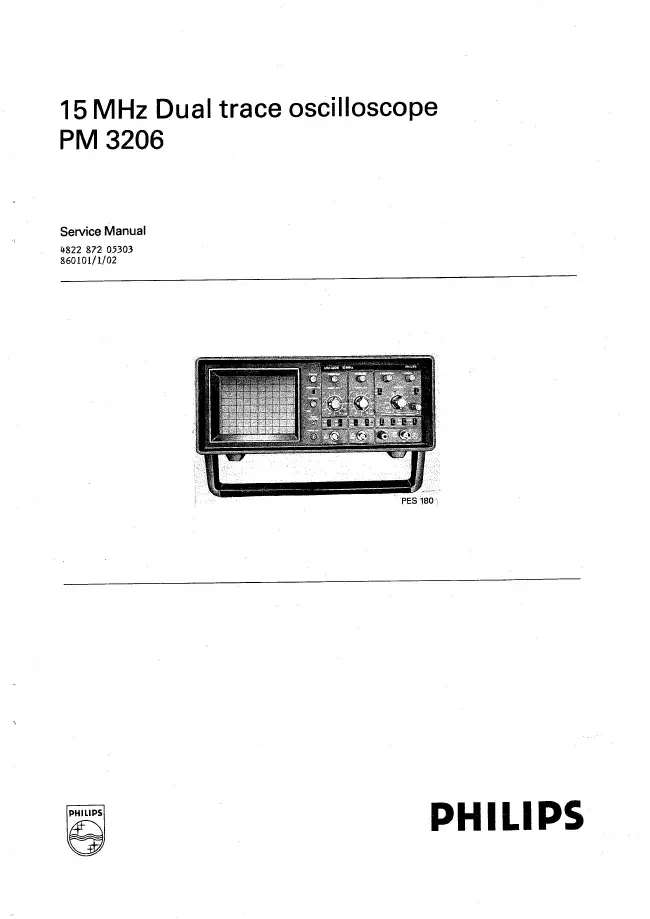
Philips - PM 3206 - Oszilloskop
Hersteller:
Gerät:
PM 3206
Datum:
1986
Kategorie:
Gruppe:
Untergruppe:

1 Handbuch

Reparaturanleitung
Dokumenttyp:
Reparaturanleitung
Seitenanzahl:
134
Größe:
13,0 MB
Sprache:
englisch
Revision:
Dokument-ID:
4822 872 05303
Datum:
Januar 1986
Qualität:
Gescanntes Dokument, alles ist lesbar.
Upload Datum:
31. Juli 2020
MD5:
e969e412-b523-186e-c8b1-e285ec07aaf7
Downloads:
916

Informationen

1. GENERAL INFORMATION 1.1. Safety Precautions 1 1.2. Caution and warning statements 1 1.3. Symbols 1 1.4. Impaired Safety Protection 1 1.5. General clauses 1 1.6. Characteristics 3 1.6.1. CRT 3 1.6.2. Vertical or Y-axis 3 1.6.3. Horizontal or X-axis 3 1.6.4. Horizontal Amplifier 4 1.6.5. Time Base 4 1.6.6. Triggering 4 1.6.7. Z-MOD input 4 1.6.8. Calibration 4 1.6.9. Power 4 1.6.10. .Environmental Capabilities 4 2. CIRCUIT DESCRIPTIONS 2.1. Block diagram description 2.1.1. Vertical Deflection 2.1.2. Triggering and Horizontal Deflection 2.1.3. CRT Display Section 9 2.1.4 Power Supply 9 2.2. Description of the vertical section 10 2.2.1. Input coupling stage 10 2.2.2. High Impedance attentuator 10 2.2.3. Preamplifier 10 2.2.4. Switched Amplifier 11 2.2.5. Channel flipflop and logic circuits 11 2.2.6. Final Amplifier 12 2.3. Horizontal deflection and Time Base 12 2.3.1. CH. A trigger pick off 12 2.3.2. CH. B trigger pick off 12 2.3.3. External trigger Amplifier 12 2.3.4. Trigger source selector Amplifier 13 2.3.5. Level Control 13 2.3.6. Comparator and sweep gating logic 13 2.3.7. T.V. slope selector 13 2.3.8. T.V. sync separator 13 2.3.9. Time Base and Hold-off Circuit 14 2.3.10.X-Deflection Selector 15 2.3.11. Final X Amplifier 15 2.4. CRT display section 15 2.4.1. Z Amplifier 15 2.4.2. High voltage supply 15 2.4.3. Trace Rotation 15 2.5 Power Supply 16 3. DISMANTLING THE INSTRUMENT 17 3.1. General Information 17 3.2. Removing the top and bottom covers 17 3.2.1. Remounting the top cover 17 3.3. Access to parts for checking and adjusting procedure 17 4. PERFORMANCE CHECK 20 4.1. General Information 20 4.2. Preliminary settings of the controls 20 4.3. Recommended test equipment 20 4.4. Checking Procedure 21 4.4.1. Power On 21 4.4.2. CRT section 21 4.4.3. Vertical Axis 21 4.4.4. Horizontal Axis 23 4.4.5. Horizontal Amplifier 24 4.4.6. Triggering 25 4.4.7. Calibration 25 5. CHECKING AND ADJUSTING 28 5.1. General Information 28 5.2. Recommended test equipment 28 5.3. Preliminary settings of the controls 28 5.4. Table of Adjustments 29 6. CORRECTIVE MAINTENANCE 32 6.1. Replacements 6.1.1. Replacing the mains fuse 33 6.1.2. Replacing mains cord or Transformer 33 6.1.3. Removing and replacing components on the main PCB 33 6.1.4. Removing and replacing components on the Control Unit 33 6.1.5. Replacing the CRT 34 6.2. Special Tools 35 6.2.1. Trimming Tool Kit 35 6.3. Recalibration after repair 36 6.4. Instrument repackaging 36 6.5. Trouble-shooting 36 6.5.1. Introduction 36 6.5.2. Troubleshooting hints 36 6.6. Adaption of mains voltage 37

mehr