.....obsolete Bedienungsanleitungen, eine Menge Reparaturanleitungen, kostenlose Serviceanleitungen, seltene Schaltpläne, nützliche Serviceanleitungen, pdf-Bücher, Reparaturanleitungen, verlorene Bedienungsanleitungen, alte Handbücher, tonnenweise Teilelisten, versteckte Service Bulletins, Ihre Bedienungsanleitungen, informative Reparaturtipps, komplette Demontageanleitungen.....


Wonach suchen Sie?


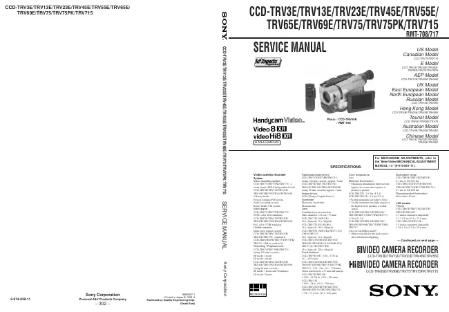
Sony - CCD-TRV23E - Videokamera
Hersteller:
Gerät:
CCD-TRV23E
Datum:
1998
Kategorie:
Gruppe:
Untergruppe:

Informationen

Video camera recorder System Video recording system CCD-TRV75 TRV75PK/TRV715 : 4 rotary heads (SP/LP independent heads) CCD-TRV3E TRV13E/TRV23E/ TRV45E/TRV55E/TRV65E/TRV69E : 2 Rotary heads Helical scanning FM system Audio recording system Rotary heads, FM system Video signal CCD-TRV75 TRV75PK/TRV715 : NTSC color, EIA standards CCD-TRV3E TRV13E/TRV23E/ TRV45E/TRV55E/TRV65E/TRV69E : PAL color CCIR standards Usable cassette 8mm video format cassette CCD-TRV3E TRV13E/TRV23E/ TRV45E/TRV55E : standard 8 CCD-TRV65E 69E/TRV75/TRV75PK/ TRV715 : Hi8 or standard 8 Recording / Playback time CCD-TRV75 TRV75PK/TRV715 : (using 120 min. cassette) SP mode: 2 hours LP mode: 4 hours CCD-TRV3E TRV13E/TRV23E/ TRV45E/TRV55E/TRV65E/TRV69E : (using 90 min. cassette) SP mode: 1 hours and 30 minutes LP mode: 3 hours Fastforward/rewind time CCD-TRV75 TRV75PK/TRV715 : (using 120 min. cassette) Approx. 5 min CCD-TRV3E TRV13E/TRV23E/ TRV45E/TRV55E/TRV65E/TRV69E : (using 90 min. cassette) Approx. 5 min. Image device CCD (Charge Coupled Device) Viewfinder Electronic viewfinder Monochrome Lens Combined power zoom lens Filter diameter 17/16 in. (37 mm) CCD-TRV13E (AEP,UK) : 16 x (Optical), 32 x (Digital) CCD-TRV13E (EE,NE,RU) : 16 x (Optical), 160 x (Digital) CCD-TRV65E (AEP,UK)/TRV75 (US, CND)/TRV715 : 18 x (Optical), 72 x (Digital) CCD-TRV23E TRV45E/TRV55E/ TRV65E (EE,NE,RU,E,AUS,HK,CN)/ TRV75 (E, JE)/TRV75PK : 18 x (Optical), 220 x (Digital) Focal distance CCD-TRV3E 13E : 3/16 - 2 5/8 in. (4.1 - 65.6 mm) CCD-TRV23E TRV45E/TRV55E/ TRV65E/TRV69E/TRV75/TRV75PK/ TRV715 : 3/16 - 8 in. (4.1 - 73.8 mm) When converted to a 35 mm still camera CCD-TRV3E TRV13E : 1 9/16 - 24 7/8 in. (39.4 - 630 mm) CCD-TRV23E 1 9/16 - 28 in. (39.4 - 709 mm) CCD-TRV45E TRV55E/TRV65E/ TRV69E/TRV75/TRV75PK/TRV715 : 1 7/8 - 33 1/2 in. (47.2 - 850 mm) Color temperature Auto Minimum illumination* * Minimum illumination expresses the light level a camcoder requires to produce a picture CCD-TRV23E 0.4 lux (F 1.4) CCD-TRV3E 13E : 0.4 lux (F1.4) (*Visible minimum low light 0.2 lux) * Visible minimum low light expresses the light level to produce a visible signal CCD-TRV45E TRV55E/TRV65E/ TRV69E/TRV75/TRV75PK/TRV715 : 0.7 lux (F 1.4) CCD-TRV23E TRV45E/TRV55E/ TRV65E/TRV69E/TRV75/TRV75PK/ TRV715 : 0 lux (in NightShot mode)* * Object invisible for the dark can be shot with infrared lighting. Illumination range CCD-TRV3E TRV13E/TRV23E : 0.4 lux to 100,000 lux CCD-TRV45E TRV55E/TRV65E/ TRV69E/TRV75/TRV75PK/TRV715 : 0.7 lux to 100,000 lux Recommended illumination More than 100 lux LCD screen Picture CCD-TRV3E TRV13E/TRV23E/ TRV65E/TRV69E : 2.5 inches measured diagonally 2 x 1 1/2 in.(50.3 x 37.4 mm) CCD-TRV45E TRV55E : 3.5 inches measured diagonally 2 7/8 x 2 in.(72.4 x 50.4 mm)

mehr

1 Handbuch

Reparaturanleitung
Dokumenttyp:
Reparaturanleitung
Seitenanzahl:
188
Größe:
22,9 MB
Sprache:
englisch
Revision:
Dokument-ID:
9-974-038-11
Datum:
Juli 1998
Qualität:
Elektronisches Dokument, kein Scan, sehr gut lesbar.
Upload Datum:
28. Januar 2017
MD5:
e1d20edb-ffba-b728-476f-bb4283261fbd
Downloads:
7340
Downloads letzter Monat:
29

Informationen

SERVICE NOTE 1. Power Supply During Repairs ... 5 2. To Take out a Cassette when not Eject (Force Eject) ... 5 Self-Diagnosis Function 1. Self-diagnosis function ... 6 2. Self-diagnosis Display ... 6 3. Service Mode Display ... 6 3-1. Display Method ... 6 3-2. Switching of Backup No. ... 6 3-3. End of Display ... 6 4. Self-diagnosis Code Table ... 7 1. GENERAL Using this manual ... 1-1 Checking supplied accessories ... 1-1 Installing and Charging the battery pack ...1-1 Inserting a cassette ...1-2 Camera recording ... 1-2 Hints for better Shooting ...1-4 Checking the recorded picture ...1-5 Playing back a tape ... 1-5 Searching for the end of the picture ... 1-6 Using alternative power sources ... 1-6 Changing the mode settings ... 1-7 Shooting with backlighting ...1-8 Using the FADER function ...1-8 Shooting in the dark (NightShot) ... 1-9 Using the wide mode function ...1-9 Using the PROGRAM AE function ...1-9 Focusing manually ...1-10 Enjoying picture effect ...1-10 Adjusting the exposure ...1-11 Superimposing a title ...1-11 Making your own titles ...1-12 Recording with the date/time ...1-12 Optimizing the recording condition ...1-12 Releasing the STEADY SHOT function ...1-13 Watching on a TV creen ...1-13 Editing onto another tape ...1-13 Recording from a VCR or TV 1-14 Changing the lithium battery in the camcoder ...1-14 Resetting the date and time ...1-14 Simple setting of clock by time difference ...1-15 Usable cassettes and playback modes ...1-15 Tips for using the battery pack ...1-15 Maintenance information and precautions ...1-16 Using your camcorder abroad ...1-17 Self-diagnosis display ...1-17 Identifying the parts ...1-18 Warning Indicators ...1-20 TABLE OF CONTENTS 2. DISASSEMBLY 2-1. Removal of Front Panel Block ... 2-1 2-2. Removal of Cabinet (R) Block ... 2-2 2-3. Removal of EVF Block-1... 2-2 2-4. Removal of LCD Block (3/3.5 inch) ...2-2 2-5. Removal of LCD Block (2.5 inch) ... 2-2 2-6. Removal of CF-51 (CF-50) Board and Control Switch Block (MR-8500)/(MF-8500) ... 2-3 2-7. Removal of EVF Block-2... 2-3 2-8. Removal of Cabinet (L) Block and Battery Panel Block ... 2-4 2-9. Removal of Cassette Lid Assembly ... 2-4 2-10. Removal of Control Switch Block (FK-8500) ... 2-4 2-11. Removal of Zoom Lens Block ... 2-5 2-12. Removal of DD-105 Board and PJ-84 (PJ-83) Board ...2-5 2-13. Removal of VC-195 and SE-67 (SE-66) Board ... 2-5 2-14. Service Position ... 2-6 2-15. Circuit Board Location ... 2-7 3. BLOCK DIAGRAMS 3-1. Overall Block Diagram ... 3-1 3-2. Camera/Video 1 Block Diagram ...3-5 3-3. VTR/Camera Control Block Diagram ... 3-9 3-4. Servo Block Diagram ... 3-12 3-5. Mode Control Block Diagram ...3-15 3-6. Audio Block Diagram ...3-19 3-7. LCD CCD-TRV23E TRV45E/TRV55E/TRV65E/TRV69E/ TRV75/TRV75PK/TRV715) Block Diagram ...3-23 3-8. LCD CCD-TRV3E TRV13E) Block Diagram ... 3-26 3-9. B/W EVF Block Diagram ...3-29 3-10. Power Block Diagram ...3-33 4. PRINTED WIRING BOARDS AND SCHEMATIC DIAGRAMS 4-1. Frame Schematic Diagram (1) ...4-1 • Frame Schematic Diagram (2) ... 4-4 4-2. Printed Wiring Boards and Schematic Diagrams ...4-7 • CD-197/198 (CCD Imager) (2.5 Inch LCD, 3 Inch/3.5 Inch LCD Model) Board ...4-8 • VC-195 (Camera, Y/C Processor, IN/OUT, REC/PB Head Amp, Servo/System Control, Servo, Audio, IR Transmiter, Mode Control) Board ...4-10 • VC-195 (Camera 1) Board ...4-17 • VC-195 (Camera 2) Board ...4-19 • VC-195 (Y/C Process) Board ...4-23 • VC-195 (IN/OUT) Board ...4-27 • VC-195 (REC/PB Head Amp) Board...4-31 • VC-195 (Servo/System Control) Board ...4-35 • VC-195 (Servo) Board ...4-38 • VC-195 (Audio) Board ...4-41 • VC-195 (IR Transmiter) Board ...4-46 • VC-195 (Mode Control) Board ...4-49 • SE-67/66 (Steady Shot) (2.5 Inch, 3 Inch/3.5 Inch LCD Model) Board ...4-52 • PJ-83/84 (AV IN/OUT) (2.5 Inch, 3 Inch/3.5 Inch LCD Model) Board ...4-55 • MA-331 (Stereo Mic, Laser Link) (2.5 Inch LCD Model) Board ...4-58 • MA-312 (Stereo Mic, Laser Link) (3 Inch/3.5 Inch LCD Model) Board ...4-59 • CF-50 (Control (2.5 Inch LCD Model)) Board ...4-64 • CF-51 (Control (3 Inch/3.5 Inch LCD Model)) Board ..4-73 • Control Switch Block (FK-8500/SS-8500) ...4-77 • PD-92 (RGB Decorder, LCD Drive, Back Light LCD (2.5 Inch LCD Model)) Board ...4-78 • PD-92 (RGB Decorder) Board ...4-81 • PD-92 (LCD Drive) Board ...4-84 • PD-92 (Back Light) Board ...4-87 • PD-92 (LCD) Board ...4-88 • PD-93 (RGB Decorder, LCD Drive, Back Light LCD (3 Inch/3.5 Inch LCD Model)) Board ...4-90 • PD-93 (RGB Decorder) Board ...4-93 • PD-93 (LCD Drive) Board ...4-96 • PD-93 (Back Light) Board ...4-99 • PD-93 (LCD) Board ...4-100 • VF-99 (B/W EVF (B/W EVF Model)) Board ...4-103 • DD-105 (Power) Board ...4-108 5. ADJUSTMENTS 5-1. CAMERA SECTION ADJUSTMENTS ...5-1 1-1. Preparations before Adjustment (Camera Section) ...5-1 1-1-1. List of Service Tools ... 5-1 1-1-2. Preparations ... 5-2 1-1-3. Precautions ... 5-5 1. Setting the Switch ... 5-5 2. Adjusting Procedure ... 5-5 3. Subject ... 5-5 1-1-4. Adjusting Remote Commander ... 5-6 1. Using the adjusting remote commander ...5-6 2. Precautions upon using the adjusting remote commander ... 5-6 1-1-5. Data Processing ... 5-7 1-2. Initialization of D, E, F Page Data ...5-8 1. Initialization of D, E, F Page Data ...5-8 2. Modification of D, E, F Page Data ... 5-8 3. D Page Table ... 5-9 4. F Page Table ...5-10 5. E Page Table ...5-12 1-3. Camera System Adjustments ...5-14 1. G-CAM flip Adjustment ... 5-14 2. Hall Adjustment ...5-15 3. Flange Back Adjustment ... 5-16 3-1. Flange Back Adjustment (1) ... 5-16 3-2. Flange Back Adjustment (2) ... 5-16 4. Flange Back Check ... 5-17 5. Picture Frame Setting ...5-17 6. Color Reproduction Adjustment ... 5-18 7. IRIS IN/OUT Adjustment ... 5-19 8. MAX GAIN Adjustment ... 5-19 9. Auto White Balance Standard Data Input ... 5-20 10. Auto White Balance Adjustment ... 5-20 11. White Balance Check ...5-21 12. Angular Velocity Sensor Sensitivity Adjustment ...5-22 CCD-TRV45E TRV55E/TRV65E/TRV69E/TRV75/ TRV75PK/TRV715) 1-4. Monochrome Electronic Viewfinder System Adjustments ... 5-23 1-4-1. Horizontal Slant Check ... 5-23 1-4-2. Centering Adjustment ... 5-23 1-4-3. Focus Adjustment ...5-23 1-4-4. Aberration Adjustment ...5-24 1-4-5. Horizontal Amplitude Adjustment (VF-99 board) ..5-24 1-4-6. Vertical Amplitude Adjustment (VF-99 board) ... 5-25 1-4-7. Brightness Adjustments (VF-99 board) ...5-25 1-4-8. Horizontal Amplitude, Vertical Amplitude, Focus Check ...5-25 1-5. LCD System Adjustment ...5-26 1. LCD initial data input ... 5-26 2. VCO adjustment (PD-92/93 board) ...5-27 3. D range adjustment (PD-92/93 board) ...5-27 4. Bright adjustment (PD-92/93 board) ... 5-28 5. Contrast adjustment (PD-92/93 board) ... 5-28 6. V-COM level adjustment (PD-92/93 board) ... 5-29 7. Color adjustment (PD-92/93 board) ...5-29 8. V-COM adjustment (PD-92/93 board) ...5-30 9. White balance adjustment (PD-92/93 board) ...5-30 5-2. MECHANICAL SECTION ADJUSTMENT ... 5-31 2-1. Operating without a Cassette ...5-31 2-2. Tape path Adjustment ... 5-31 1. Preparations for adjustments ... 5-31

mehr