Sony - KDL-52XBR6 - Fernseher
Hersteller:
Gerät:
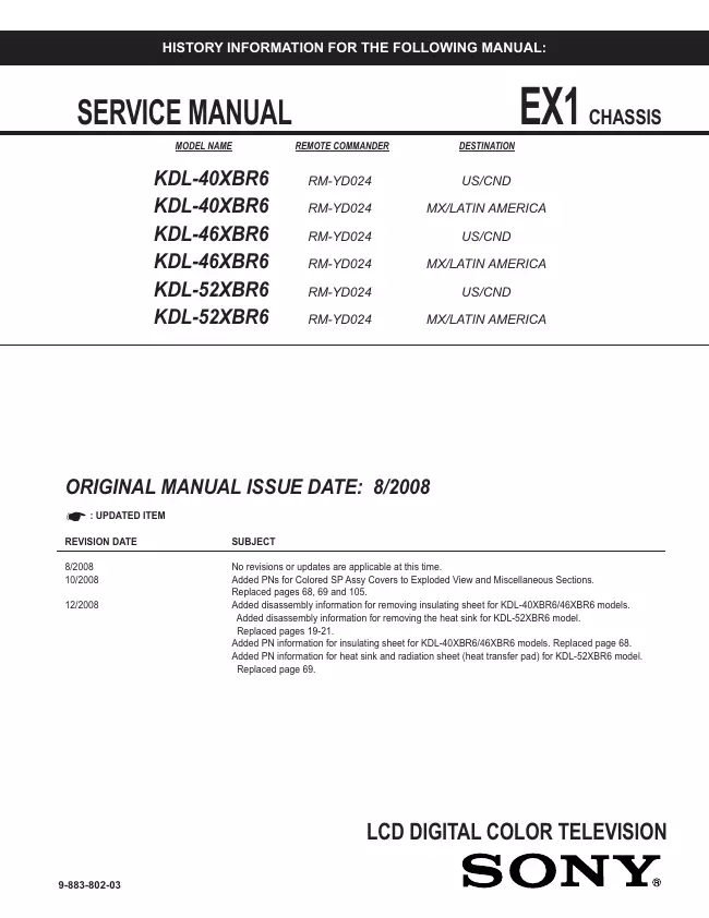
KDL-52XBR6
Datum:
2008
Kategorie:
Gruppe:
Untergruppe:
Informationen
2 Handbücher
Reparaturanleitung
Dokumenttyp:
Reparaturanleitung
Seitenanzahl:
107
Größe:
15,5 MB
Sprache:
Englisch
Revision:
Dokument-ID:
9-883-802-03
Datum:
Dezember 2008
Qualität:
Elektronisches Dokument, kein Scan, sehr gut lesbar.
Upload Datum:
23. September 2018
MD5:
22df70c0-72fc-47a3-5d4a-08a2d1b47785
Downloads:
1894
Reparaturanleitung
Dokumenttyp:
Reparaturanleitung
Seitenanzahl:
107
Größe:
15,5 MB
Sprache:
Englisch
Revision:
Dokument-ID:
9-883-802-03
Datum:
Dezember 2008
Qualität:
Elektronisches Dokument, kein Scan, sehr gut lesbar.
Upload Datum:
23. September 2018
MD5:
22df70c0-72fc-47a3-5d4a-08a2d1b47785
Downloads:
1894