Sony - KV-27FV300 - Fernseher
Hersteller:
Gerät:
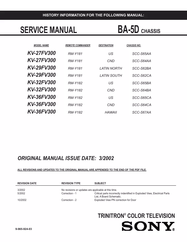
KV-27FV300
Datum:
2002
Kategorie:
Gruppe:
Untergruppe:
Informationen
Introducing the FD Trinitron WEGA ® Features
Some of the features you will enjoy include:
FD Trinitron Flat CRT — Technologically advanced tube
delivers a picture with uncompromising
accuracy and outstanding image detail.
Y, PB , P R Inputs — A component video input connection for
a superior picture quality
(480i only).
Surround — Simulates theater quality sound for stereo programs.
Parental Control (V-Chip) — A tool to help parents monitor
what their children watch on TV by
establishing rating limits.
Picture in Picture (PIP) — Allows you to view two programs
simultaneously
(KV-27FS200, KV-32FS200, KV-36FS200 only).
Favorite Channels — Instant access to your favorite channels
with the touch of a button.
Info Banner — A new, convenient feature that displays the
name and the remaining time of the
current program viewed, if available.
Universal Remote Control — Program your remote control to
operate your connected cable box,
VCR, digital satellite receiver, or DVD player.
Energy Star® — Meets the Energy Star guidelines for energy
efficiency.
Front Panel Controls — Allows access to the on-screen menus
without the use of a remote
control.
Front A/V Inputs — A quick connection for video games,
camcorders or stereo/mono equipment.
2 Handbücher
Reparaturanleitung
Dokumenttyp:
Reparaturanleitung
Seitenanzahl:
205
Größe:
12,7 MB
Sprache:
Englisch
Revision:
Dokument-ID:
9-965-924-03
Datum:
Qualität:
Elektronisches Dokument, kein Scan, sehr gut lesbar.
Upload Datum:
15. Januar 2014
MD5:
39eaf192-ebb9-6341-4f4d-e75af6be9d89
Downloads:
3680
Reparaturanleitung
Dokumenttyp:
Reparaturanleitung
Seitenanzahl:
252
Größe:
8,8 MB
Sprache:
Englisch
Revision:
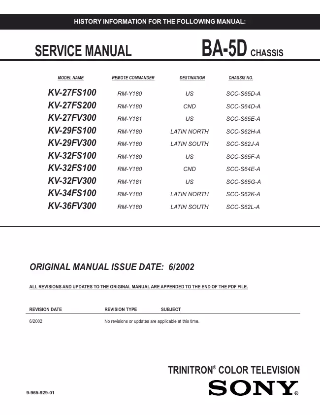
Dokument-ID:
9-965-929-01
Datum:
Juni 2002
Qualität:
Elektronisches Dokument, kein Scan, sehr gut lesbar.
Upload Datum:
3. Oktober 2018
MD5:
0738d33a-ce8d-7078-a051-28724c778dcd
Downloads:
3287