Marconi - TF 868B - Other
Manufacturer:
No picture available!
Maybe you can
upload a pic
for the
Marconi TF 868B ?
If you have any other manuals for the
Marconi TF 868B
you can
upload the files here.
.
Equipment:
TF 868B
Date:
1960
Category:
Group:
Sub Group:
Information
GENERAL
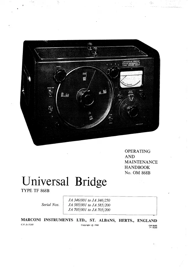
The Universal Bridge Type TF 868B is a direct-reading instrument which
measures values of inductance from 1 (j-H to 100 henrys, capacitance from 1
¡x|xF to 100 nF, and resistance from 0-1 ohm to 100 MQ.
The instrument employs a single dial for the measurement of inductance,
capacitance, and resistance values. Changing the setting of the lcr and range
selector switches automatically changes the dial calibration together with the
bridge circuit conditions to suit the component under test.
For inductance and capacitance measurement the bridge is energized by an
RC oscillator-amplifier that can be switched to 1 kc/s or 10 kc/s. The out-of-
balance bridge voltage, after amplification and detection, is displayed by a
moving-coil meter on the front panel. Measurement of inductance and
capacitance is normally made at 1 kc/s; however, the use of 10 kc/s is an
advantage, for example, when evaluating low-Q inductors.
When measuring resistance, a d.c. voltage is applied to the bridge. The out-
of-balance bridge voltage is interrupted at twice the supply frequency by
means of a vibrator (or chopper) before being applied to the amplifier-
detector circuits. This system gives a high degree of sensitivity without the
use of a high potential across the component.
A control, phase balance, is provided for balancing out the resistive
component when inductance and capacitance are being measured. This
control has two scales which are calibrated in Q and tan 8 respectively. The
scale in use is determined by the setting of the q-tan S switch. The Q scale is
calibrated from 0-1 to 10, and the tan 8 scale from 0-001 to 0-1.
Q is normally used for inductors and tan S for capacitors.
Q, also known as magnification factor or storage
factor, is the ratio of reactance to resistance in a series circuit, or
susceptance to conductance in a parallel circuit.
Tan 8, also known as loss tangent, dissipation factor or D, is the reciprocal of
Q.
Power factor, another term commonly used to express capacitor losses, is the
ratio of resistance to impedance, or conductance to admittance, and differs
from tan S by less than 1 % when their values are less than 0.15.
For convenience, an instruction plate is fitted which interrelates values of Q
and tan S together with effective series and parallel values. The plate also
gives summarized instructions for operating the Bridge.
The test terminals are located on top of the instrument; the flat top provides a
useful insulated platform for supporting the component to be tested.
When measuring inductive components, the usefulness of the instrument
may be extended by the use of the D.C. Choke Adaptor, described below.
1.2 OPTIONAL ACCESSORY D.C. Choke Adaptor Type TM 6113
With this Adaptor fitted to the Bridge terminals, an inductor in the range 100
mH to 100 henrys can be measured at 1 kc/s while a d.c. current up to 200
mA is passed through it from an external source.
The essential function of the Adaptor is to isolate the Bridge from the d.c.
supply, while at the same time preventing the external circuit from appearing
as an undesirable load across the test terminals. When making a
measurement, the introduced error is not likely to be greater than 3 %; this
can be ignored, or eliminated by a simple substitution method.
1 Manual
Service and user manual
Manual type:
Service and user manual
Pages:
46
Size:
2.6 MB
Language:
english
Revision:
Manual-ID:
OM 868B
Date:
January 1960
Quality:
Scanned document, reading partly badly, partly not readable.
Upload date:
Jan. 6, 2019
MD5:
274673fd-c966-8727-79ad-87821c6da607
Downloads:
250