Aiwa - HV-FX970 - Video cassette recorder
Manufacturer:
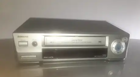
Image 1 of 1 provided by: gigastor
If you have any other photos or manuals for the
Aiwa HV-FX970
you can
upload the files here.
Equipment:
HV-FX970
Date:
Category:
Group:
Sub Group:
Information
2 Manuals
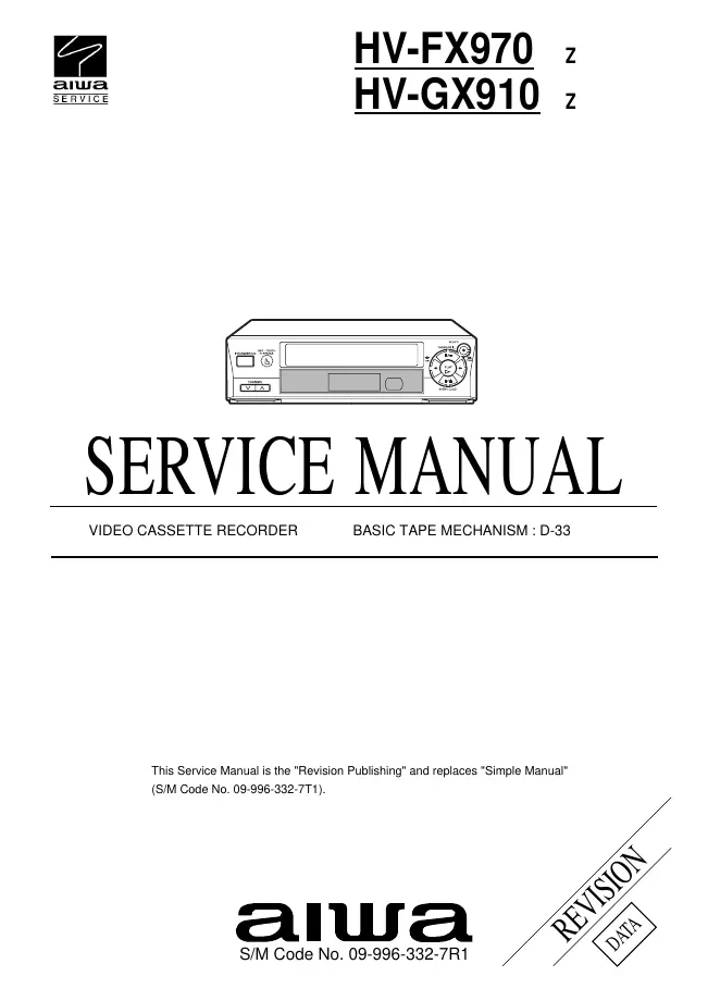
Service manual
Manual type:
Service manual

Pages:
67
Size:
5.3 MB
Language:
english
Revision:
Manual-ID:
09-996-332-6R1
Date:
Quality:
Electronic document, no scan, very well readable.
Upload date:
Feb. 5, 2017
MD5:
68e07657-215c-91bf-a934-7a2fbcaf57e9
Downloads:
1678
Service manual
Manual type:
Service manual
Pages:
69
Size:
7.0 MB
Language:
english
Revision:
Manual-ID:
09-996-332-7R1
Date:
Quality:
Electronic document, no scan, very well readable.
Upload date:
Oct. 10, 2017
MD5:
adf8fcbe-daf6-2060-e9fc-7cf54da3d0c6
Downloads:
949