Fluke - 123 - ScopeMeter
Manufacturer:
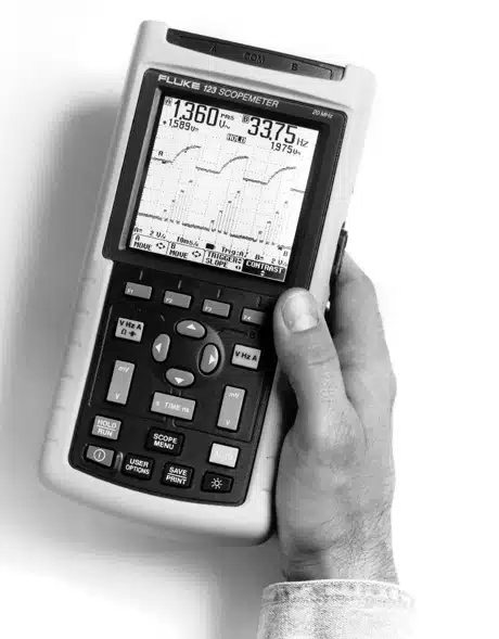
Image 1 of 1
If you have any other photos or manuals for the
Fluke 123
you can
upload the files here.
Equipment:
123
Date:
1997
Category:
Group:
Sub Group:
Information
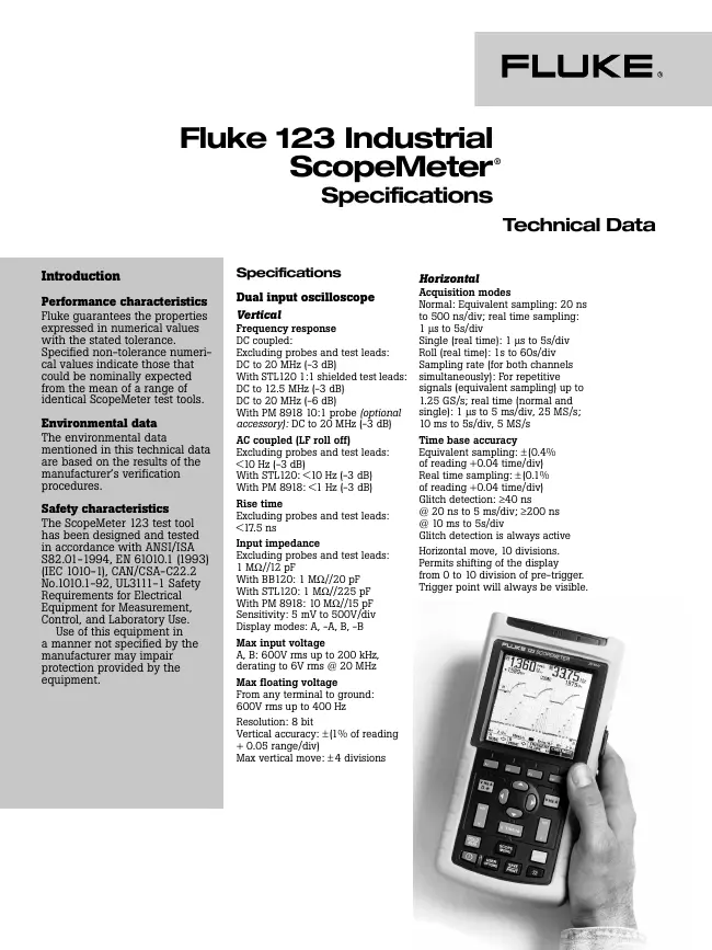
Dual input oscilloscope
Vertical
Frequency response
DC coupled:
Excluding probes and test leads:
DC to 20 MHz (-3 dB)
With STL120 1:1 shielded test leads:
DC to 12.5 MHz (-3 dB)
DC to 20 MHz (-6 dB)
With PM 8918 10:1 probe (optional
accessory): DC to 20 MHz (-3 dB)
AC coupled (LF roll off)
Excluding probes and test leads:
<10 Hz (-3 dB)
With STL120: <10 Hz (-3 dB)
With PM 8918: <1 Hz (-3 dB)
Rise time
Excluding probes and test leads:
<17.5 ns
Input impedance
Excluding probes and test leads:
1 MW//12 pF
With BB120: 1 MW//20 pF
With STL120: 1 MW//225 pF
With PM 8918: 10 MW//15 pF
Sensitivity: 5 mV to 500V/div
Display modes: A, -A, B, -B
Max input voltage
A, B: 600V rms up to 200 kHz,
derating to 6V rms @ 20 MHz
Max floating voltage
From any terminal to ground:
600V rms up to 400 Hz
Resolution: 8 bit
Vertical accuracy: ±(1% of reading
+ 0.05 range/div)
Max vertical move: ±4 divisions
Horizontal
Acquisition modes
Normal: Equivalent sampling: 20 ns
to 500 ns/div; real time sampling:
1 ms to 5s/div
Single (real time): 1 ms to 5s/div
Roll (real time): 1s to 60s/div
Sampling rate (for both channels
simultaneously): For repetitive
signals (equivalent sampling) up to
1.25 GS/s; real time (normal and
single): 1 ms to 5 ms/div, 25 MS/s;
10 ms to 5s/div, 5 MS/s
Time base accuracy
Equivalent sampling: ±(0.4%
of reading +0.04 time/div)
Real time sampling: ±(0.1%
of reading +0.04 time/div)
Glitch detection: ³40 ns
@ 20 ns to 5 ms/div; ³200 ns
@ 10 ms to 5s/div
Glitch detection is always active
Horizontal move, 10 divisions.
Permits shifting of the display
from 0 to 10 division of pre-trigger.
Trigger point will always be visible.
7 Manuals
Service manual
Manual type:
Service manual
Pages:
170
Size:
5.3 MB
Language:
english
Revision:
3
Manual-ID:
4822 872 05375
Date:
Quality:
Electronic document, no scan, very well readable.
Upload date:
Nov. 29, 2014
MD5:
d1e4ef72-a9bc-1d3f-a26a-274826207797
Downloads:
804
Service manual
Manual type:
Service manual
Pages:
96
Size:
2.0 MB
Language:
english
Revision:
Manual-ID:
4822 872 05398
Date:
Quality:
Electronic document, no scan, very well readable.
Upload date:
Nov. 29, 2014
MD5:
c87ad484-e83e-45f4-a080-37ec9a5bb2fb
Downloads:
1607
Datasheet
Manual type:
Datasheet
Pages:
4
Size:
729.8 KB
Language:
english
Revision:
A
Manual-ID:
J0661
Date:
Quality:
Electronic document, no scan, very well readable.
Upload date:
Nov. 30, 2014
MD5:
7d2cac54-6276-9204-8572-f02481b27222
Downloads:
602
User manual
Manual type:
User manual

Pages:
83
Size:
1.8 MB
Language:
english
Revision:
Manual-ID:
Date:
Quality:
Electronic document, no scan, very well readable.
Upload date:
Jan. 26, 2016
MD5:
06bfdf87-5407-2d73-3a7d-08576f198abd
Downloads:
915
Service manual
Manual type:
Service manual
Pages:
77
Size:
1.6 MB
Language:
english
Revision:
4
Manual-ID:
4822 872 00743
Date:
Quality:
Electronic document, no scan, very well readable.
Upload date:
Jan. 26, 2016
MD5:
39798c0a-3135-4b15-04be-d94ce32f6d3c
Downloads:
547
Service manual
Manual type:
Service manual
Pages:
174
Size:
7.1 MB
Language:
english
Revision:
Manual-ID:
4822 872 05389
Date:
February 2003
Quality:
Scanned document, all readable.
Upload date:
July 22, 2020
MD5:
798e0507-5681-c736-483f-f7a88df7f5da
Downloads:
373
User manual
Manual type:
User manual
Pages:
98
Size:
119.0 KB
Language:
english
Revision:
Manual-ID:
Date:
Quality:
Electronic document, no scan, very well readable.
Upload date:
March 20, 2023
MD5:
a339c682-aa67-a35f-8c3b-6ea3874aa0a7
Downloads:
0