Grundig - LEEMAXX 37 P 37-4204 TOP - TV
Manufacturer:
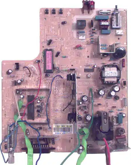
Image 1 of 1
If you have any other photos or manuals for the
Grundig LEEMAXX 37 P 37-4204 TOP
you can
upload the files here.
Equipment:
LEEMAXX 37 P 37-4204 TOP
Date:
2002
Category:
Group:
Sub Group:
Information
4 Manuals
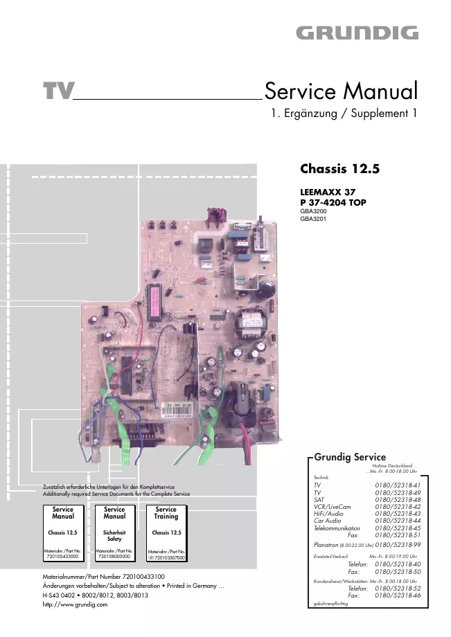
Service manual supplement
Manual type:
Service manual supplement
Pages:
4
Size:
275.6 KB
Language:
english, german
Revision:
Supplement 1
Manual-ID:
720100433100
Date:
Quality:
Electronic document, no scan, very well readable.
Upload date:
March 25, 2012
MD5:
5baf3061-25c4-bc4c-4716-62ccf554efc3
Downloads:
1065
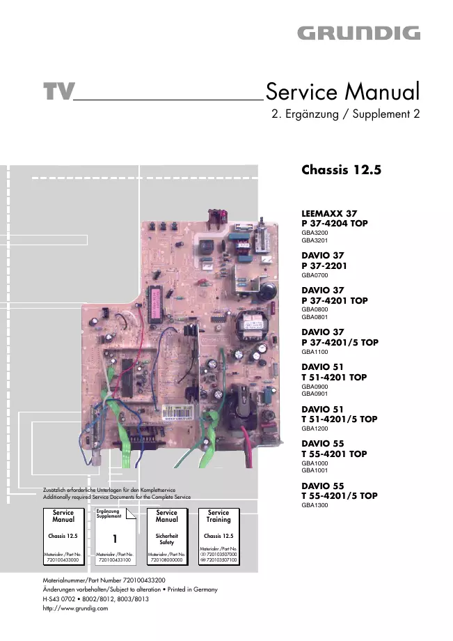
Service manual supplement
Manual type:
Service manual supplement
Pages:
4
Size:
374.7 KB
Language:
english, german
Revision:
Supplement 2
Manual-ID:
720100433200
Date:
Quality:
Electronic document, no scan, very well readable.
Upload date:
March 25, 2012
MD5:
10d12df3-1420-ae50-b136-6df74add22d4
Downloads:
4685
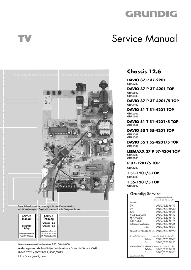
Service manual
Manual type:
Service manual
Pages:
32
Size:
3.6 MB
Language:
english, german
Revision:
first edition
Manual-ID:
720100444000
Date:
Quality:
Electronic document, no scan, very well readable.
Upload date:
March 25, 2012
MD5:
6edbc00e-7565-0e97-a868-805245c66f35
Downloads:
5698
Service manual
Manual type:
Service manual

Pages:
32
Size:
3.6 MB
Language:
english, german
Revision:
Manual-ID:
720100444000
Date:
Quality:
Electronic document, no scan, very well readable.
Upload date:
Jan. 17, 2013
MD5:
6a1e13de-b205-f7f6-e2e4-dae06ec912c3
Downloads:
5564