Grundig - TVR 5540 FR/TOP - TV
Manufacturer:

Image 1 of 9
If you have any other photos or manuals for the
Grundig TVR 5540 FR/TOP
you can
upload the files here.
Equipment:
TVR 5540 FR/TOP
Date:
2000
Category:
Group:
Sub Group:
Information
2 Manuals
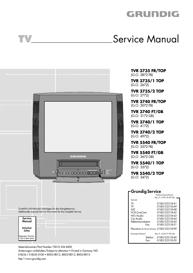
Service manual
Manual type:
Service manual
Pages:
78
Size:
7.3 MB
Language:
english, german
Revision:
first edition
Manual-ID:
72010 536 6000
Date:
Quality:
Electronic document, no scan, very well readable.
Upload date:
March 25, 2012
MD5:
f7aaf6cd-36a5-7881-8b62-51075e1f337a
Downloads:
5150
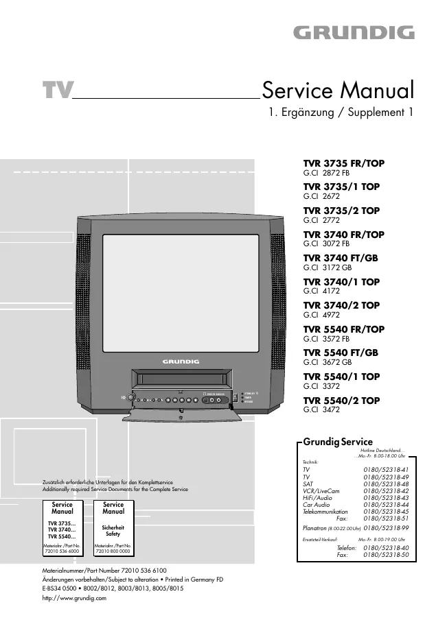
Service manual supplement
Manual type:
Service manual supplement
Pages:
32
Size:
5.5 MB
Language:
english, german
Revision:
Supplement 1
Manual-ID:
72010 536 6100
Date:
Quality:
Electronic document, no scan, very well readable.
Upload date:
March 25, 2012
MD5:
15a2d57d-777c-6999-756b-065aac786c28
Downloads:
4186