Harvey-Wells Electronic - R-9 - Receiver
Manufacturer:
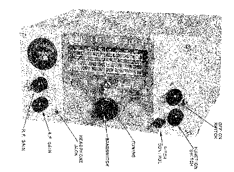
Image 1 of 3
If you have any other photos or manuals for the
Harvey-Wells Electronic R-9
you can
upload the files here.
Equipment:
R-9
Date:
1955
Category:
Group:
Sub Group:
Information
The new R-9 is a versatile Amateur Band communications
receiver, featuring performance and compactness. The overall
characteristics are such that either fixed station or mobile
operation requirements are effectively fulfilled.
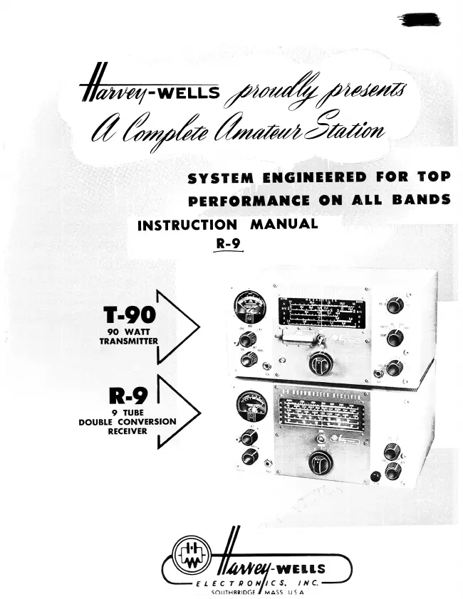
The R-9 utilizes nine tubes plus the rectifier in a double
superheterodyne circuit, providing the reception of phone
and code signals over the six main amateur bands. Calibrated
tuning is furnished for the 80 - 40, 20 - 15, and 10 and 11
meter bands.
1 Manual
Service and user manual
Manual type:
Service and user manual
Pages:
44
Size:
9.4 MB
Language:
english
Revision:
Manual-ID:
Date:
Quality:
Scanned document, reading partly badly, partly not readable.
Upload date:
Aug. 6, 2015
MD5:
f3d75717-65fe-a183-8645-a289381ae445
Downloads:
536