Huntron Instruments - HTR 1005B-1ES - Test Set
Manufacturer:
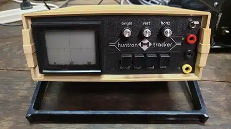
Image 1 of 1
If you have any other photos or manuals for the
Huntron Instruments HTR 1005B-1ES
you can
upload the files here.
Equipment:
HTR 1005B-1ES
Date:
1983
Category:
Group:
Sub Group:
Information
The HUNTRON TRACKER® is a special type of CRT display and
signal processing instrument that can be used to determine
the quality of certain types of electronic components.
Components are tested with a two terminal system of test
leads that are placed across the component under test. The
test leads are inserted into the TRACKER® front panel. The
TRACKER® is used to test components in a power-off
condition, and can be used to test components mounted on
printed circuit boards or other in-circuit conditions even
with components bridged by various types of resistive values.
Devices that are normally tested by the TRACKER® include the
following: semiconductor diodes, bipolar transistors, and
field effect transistors; bipolar and MOS integrated
circuits, including both analog and digital; certain types
of capacitors and inductors.
Included as standard equipment with each TRACKER® is a set
of HUNTRON® MICRO PROBES™. The MICRO PROBE™ leads plug into
the front panel test jacks. MICRO PROBES™ have special tips
so that they can be used to contact very small component
terminals and small PCB etchings without the danger of
shorting adjacent terminals and leads. Also included as
standard equipment is a common test lead which is used with
the TRACKER® in the “Comparatrace” mode.
2 Manuals
Service and user manual
Manual type:
Service and user manual
Pages:
38
Size:
1.6 MB
Language:
english
Revision:
Manual-ID:
Date:
Quality:
Scanned document, reading partly badly, partly not readable.
Upload date:
March 11, 2014
MD5:
95feef96-fbd9-5969-9bb9-def39760c589
Downloads:
1549
User manual
Manual type:
User manual
Pages:
110
Size:
2.2 MB
Language:
english
Revision:
Manual-ID:
Date:
Quality:
Scanned document, all readable.
Upload date:
March 11, 2014
MD5:
11f02491-d1b3-8b68-dfa9-1b41a965b274
Downloads:
1520