Icom - IC-449A - Transceiver
Manufacturer:
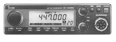
Image 1 of 1
If you have any other photos or manuals for the
Icom IC-449A
you can
upload the files here.
Equipment:
IC-449A
Date:
1991
Category:
Group:
Sub Group:
Information
1 Manual
Service manual
Manual type:
Service manual
Pages:
47
Size:
16.4 MB
Language:
english
Revision:
Manual-ID:
Date:
Quality:
Scanned document, all readable.
Upload date:
Jan. 6, 2016
MD5:
8ab7cc17-f374-76e6-b49a-4a9689a75a08
Downloads:
1149