Icom - IC-756PRO - Transceiver
Manufacturer:
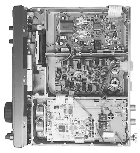
Image 1 of 7
If you have any other photos or manuals for the
Icom IC-756PRO
you can
upload the files here.
Equipment:
IC-756PRO
Date:
1999
Category:
Group:
Sub Group:
Information
•General
•Frequency coverage :
Receive 00.030–60.000 MHz*1, *2
Transmit 01.800–01.999*2
03.500–03.999*2
07.000–07.300*2
10.100–10.150*2
14.000–14.350*2
18.068–18.168*2
21.000–21.450*2
24.890–24.990*2
28.000–29.700*2
50.000–54.000*2
*1 Some frequency bands are not guaranteed.
*2 Depending on version
•Mode : USB, LSB, CW, RTTY, AM,
FM
•Number of memory : 101 (99 regular, 2 scan edges)
channels
• Antenna connector : SO-239×2 and phono
(RCA; 50 Ω)
•Temperature range : –10°C to +50°C;
+14°F to +122°F
•Frequency stability : Less than ±0.5 ppm 1 min.
after power on. (–10 to 50°C;
+14 to +122°F)
•Frequency resolution : 1 Hz
•Power supply : 13.8 V DC ±15%
•Power consumption :
Transmit Max. power 23 A
Receive Standby 3.0 A (typ.)
Max. audio 3.5 A (typ.)
•Dimensions : 340(W)×111(H)×285(D) mm
(projections not included) 133⁄8(W)×43⁄8(H)×117⁄32(D) in
•Weight (approx.) : 9.6 kg; 21 lb 3 oz
•ACC 1 connector : 8-pin DIN connector
•ACC 2 connector : 7-pin DIN connector
• CI-V connector : 2-conductor 3.5 (d) mm (1⁄8˝)
• Display : 5-inch (diagonal) TFT color
LCD
•Transmitter
•Output power (continuously adjustable):
SSB/CW/RTTY/FM 5–100 W
AM 5–40 W
• Modulation system :
SSB PSN modulation
AM Low power modulation
FM Phase modulation
•Spurious emission : 50 dB (HF bands)
60 dB (50 MHz band)
• Carrier suppression : 40 dB
•Unwanted sideband : 55 dB
suppression
•∂TX variable range : ±9.999 kHz
• Microphone connector : 8-pin connector (600 Ω)
•ELEC-KEY connector : 3-conductor 6.35(d) mm (1⁄4")
•KEY connector : 3-conductor 6.35(d) mm (1⁄4")
•SEND connector : Phono (RCA)
• ALC connector : Phono (RCA)
•Receiver
•Receive system : Triple conversion
superheterodyne system
• Intermediate frequencies:
1st 64.455 MHz
2nd 455 kHz
3rd 36 kHz
• Sensitivity (typical) :
SSB, CW, RTTY 0.16 μV (1.80–29.99 MHz)*1
(10 dB S/N) 0.13 μV (50.0–54.0 MHz)*2
AM (10 dB S/N) 13 μV (0.5–1.799 MHz)
2 μV (1.80–29.99 MHz)*1
1 μV (50.0–54.0 MHz)
FM (12 dB SINAD) 0.5 μV (28.0–29.99 MHz)*1
0.32 μV (50.0–54.0 MHz)*2
*1Pre-amp 1 is ON, *2Pre-amp 2 is ON
• Squelch sensitivity (Pre-amp: OFF):
SSB, CW, RTTY Less than 5.6 μV
FM Less than 1 μV
• Selectivity :
SSB, RTTY More than 2.4 kHz/–6 dB
(BW: 2.4 kHz) Less than 2.8 kHz/–60 dB
CW (BW: 500 Hz) More than 500 Hz/–6 dB
Less than 700 Hz/–60 dB
AM (BW: 6 kHz) More than 6.0 Hz/–6 dB
Less than 15.0 Hz/–60 dB
FM (BW: 15 kHz) More than 12.0 Hz/–6 dB
Less than 20.0 Hz/–60 dB
•Spurious and image : More than 70 dB
rejection ratio (except IF through on 50 MHz
band)
• AF output power : More than 2.0 W at 10%
(at 13.8 V DC) distortion with an 8 Ω load
• RIT variable range : ±9.999 kHz
•PHONES connector : 3-conductor 6.35 (d) mm
(1⁄4˝)
• External SP connector : 2-conductor 3.5 (d) mm
(1⁄8˝)/8Ω
•Antenna tuner
• Matching impedance range:
HF bands 16.7 to 150 Ω unbalanced
(Less than VSWR 3:1)
50 MHz band 20 to 125 Ω unbalanced
(Less than VSWR 2.5:1)
•Minimum operating : 8 W
input power
•Tuning accuracy : VSWR 1.5:1 or less
• Insertion loss : Less than 1.0 dB
(after tuning)
3 Manuals
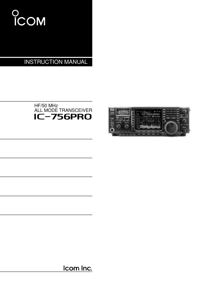
User manual
Manual type:
User manual
Pages:
84
Size:
2.0 MB
Language:
english
Revision:
Manual-ID:
A-5627H-1EX
Date:
Quality:
Electronic document, no scan, very well readable.
Upload date:
June 24, 2012
MD5:
59f922bf-2d3f-6565-381b-d3512fa76675
Downloads:
864
Service manual
Manual type:
Service manual
Pages:
93
Size:
17.3 MB
Language:
english
Revision:
Manual-ID:
S-13604HZ-C1
Date:
Quality:
Electronic document, no scan, very well readable.
Upload date:
Jan. 21, 2014
MD5:
fe59e152-2280-2b5a-bff6-184a0176b79c
Downloads:
1111
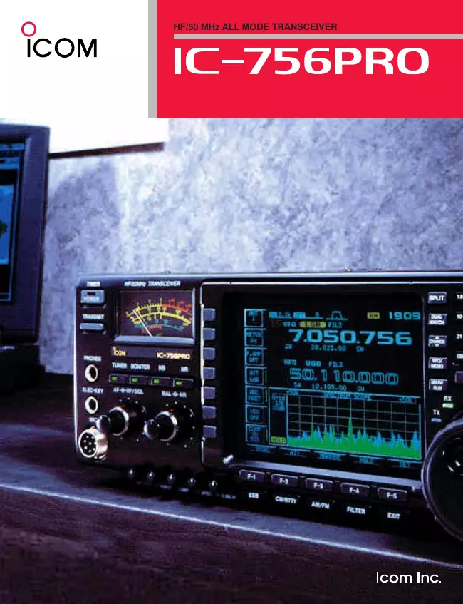
Datasheet
Manual type:
Datasheet
Pages:
7
Size:
3.5 MB
Language:
english
Revision:
Manual-ID:
00DS0020
Date:
Quality:
Electronic document, no scan, very well readable.
Upload date:
July 19, 2015
MD5:
716f7643-0b2d-a344-2ddb-fc9f7e69fd5d
Downloads:
521