Icom - IC-T7H - Transceiver
Manufacturer:
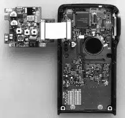
Image 1 of 4
If you have any other photos or manuals for the
Icom IC-T7H
you can
upload the files here.
Equipment:
IC-T7H
Date:
1998
Category:
Group:
Sub Group:
Information
2 Manuals
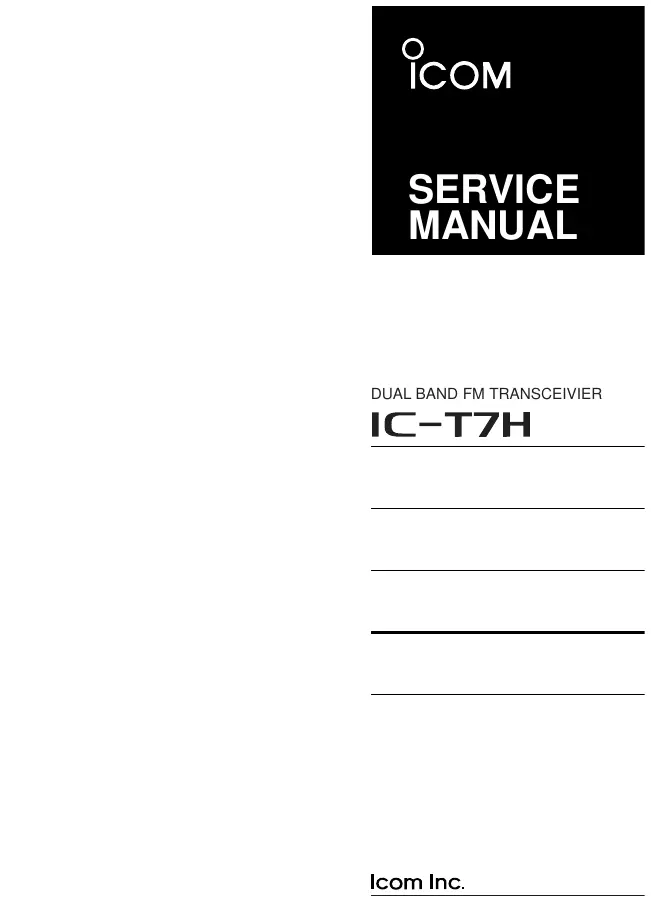
Service manual
Manual type:
Service manual
Pages:
37
Size:
1.5 MB
Language:
english
Revision:
Manual-ID:
A-5551I-S
Date:
Quality:
Electronic document, no scan, very well readable.
Upload date:
June 17, 2012
MD5:
f78c0a86-eace-48e6-87bd-b751245e9f67
Downloads:
833
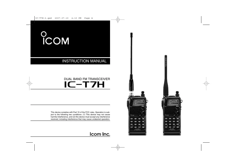
User manual
Manual type:
User manual
Pages:
36
Size:
847.2 KB
Language:
english
Revision:
Manual-ID:
A-5551D-1EX
Date:
January 2007
Quality:
Electronic document, no scan, very well readable.
Upload date:
Feb. 23, 2020
MD5:
a8ac83c5-d38d-b951-4a30-17e137638b63
Uploader:
Andre Furtado
Downloads:
181