
.....obsolete user manuals, a lot of repair manuals, free service manuals, rare schematic diagrams, usefull service instructions, pdf books, how to repair instructions, lost operating manuals, old handbooks, tons of part lists, hidden service bulletins, your instruction books, informative repair tips, complete disassembly routines.....


What are you looking for?


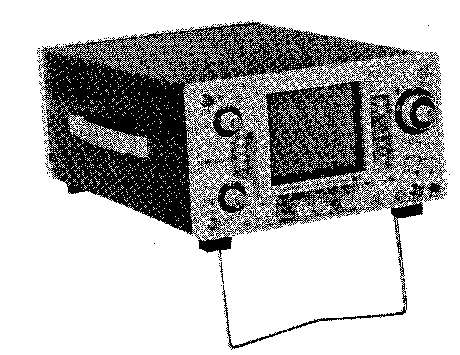
Iwatsu - SS-5705A - Oscilloscope
Manufacturer:
Equipment:
SS-5705A
Date:
Category:
Group:
Sub Group:

Information

The Oscilloscope 5702A/03A/05A/06A is an indispensable instrument for the production lines a and maintenance/servicing as well as research and development of electronic devices and equipment. This is a measuring instrument which has pursued not only functionality, but also operability, high accuracy and stability. The major features of this instrument are as follows. • The vertical deflection system, with the frequency band widths of DC to 20 MHz SS-5702A 03A), DC to 30 MHz SS-5706A DC to 40 MHz SS-5705A has the DUAL function SS-5702A 03A) which allows 2-phenomenon (in the CHOP or ALTERNATE mode) observation, and can provide the 2-phenomenon (in the CHOP or ALTERNATE mode) and 3-phenomenon (in the CHOP or ALTERNATE mode) 6-trace display. It can also measure the sum and difference of two signals (by ADD). Since the maximum input sensitivity is 1 mV/div. for both CH1 and CH2 due to the PULL x 5 MAG function, microvoltage can be also measured accurately. The horizontal deflection system has a maximum sweep rate of 50ns/div. by the PULL x 10 MAG SS-5702A 03A), of 20 ns/div. by the PULL x 5 MAG SS-5706A function, or of 10 ns/div. by the PULL x 10 MAG SS-5705A and can measure up to high-speed phenomena accurately. It is possible to have the delay sweep function (SS -5705A/06A only) and observe TV signal waveforms due to X-Y operation and TV-V, TV-H (TV-V only for SS-5702A triggering. The CRT is 6-inch (150 mm) rectangular with nonparallax internal graticule. It has a display area of 8 div. (length) x10 div. (width) (1 div. = 10 mm) and allows high-luminance waveform observatiion due to the stabilized acceleration voltage of about 2 kV SS-5702A 03A) and 12 kV SS-5705A 06A).

show more

1 Manual

Service and user manual
Manual type:
Service and user manual
Pages:
240
Size:
41.7 MB
Language:
english
Revision:
Manual-ID:
A1-311500(L)
Date:
Quality:
Scanned document, reading partly badly, partly not readable.
Upload date:
Aug. 29, 2017
MD5:
b45399ce-217c-921f-d11f-40ace24f1cd0
Downloads:
4641
Last month downloads:
19

Information

Operators Safety Summary...VII Section 1 Specifications 1-1 GENERAL...1-1 1-2 ELECTRICAL SPECIFICATIONS .. 1-2 1-3 WEIGHT AND DIMENSIONS...1-8 1-4 ENVIRONMENTAL CHARACTERISTICS...1-9 Section 2 Circuit Description 2-1 GENERAL DESCRIPTION...2-1 2-1-1 SS-5705A 5706A...2-1 2-1-2 SS-5702A 5703A...2-3 2-2 VERTICAL AXIS...2-5 2-2-1 Vertical Axis Input and Attenuator (CH1 circuit numbers are used) @[T]g...2-5 2-2-2 Preamplifier (CH1,CH2) EMU ...2-5 2-2-3 Preamplifier (CH3) [5]...2-7 2-2-4 Delay Cable Driving Amplifier (SS-5705 A only) [3]...2-8 2-2-5 Switching Circuit [3]...2-8 2-2-6 Delay Cable (SS-5705 A only) [|] ...2-10 2-2-7 Vertical Main Amplifier [4] .. 2-10 2-3 TRIGGER Generator CIRCUIT ...2-10 2-3-1 Coupling Circuit [5] ...2-11 2-3-2 TV Synchronization Signal Separation Circuit [5] ... 2-12 2-4 SWEEP SIGNAL Generator CIRCUIT ...2-12 2-4-1 A-Sweep Generator Circuit [8], @ . ...2-12 2-4-2 B-Sweep Generator Circuit [9], 01...2-16 2-5 H-CONTROL ®,[7]...2-16 2-6 HORIZONTAL Amplifier 5H...2-17 2-7 AXIS Amplifier AND CRT CIRCUIT ...2-19 2-7-1 Z-Axis Amplifier [H...2-19 2-7-2 CRT Circuit EE ...2-20 2-8 Power Supply [t4| ...2-20 2-9 Calibrator J...2-22 Section 3 Maintenance 3-1 PREVENTIVE MAINTENANCE ... 3-1 3-1-1 Cleaning...3-1 3-1-2 Storage...3-2 3-1-3 Visual Checking...3-2 3-1 -4 Periodical Check and Adjustment...3-2 3-2 TROUBLESHOOTING FLOWCHART ...3-2 3-2-1 SS-5705A 5706A Troubleshooting...3-3 3-2-2 SS-5702A 5703A Troubleshooting...3-8 3-3 BOARD REMOVAL AND REPLACEMENT INSTRUCTIONS...3-13 3-3-1 Cover Removal...3-14 3-3-2 SS-5705A 5706A ( Left Side) V Board (ATTENUATOR [Ö], CH1-CH2 PREAMP [T| [2], CONTROL [3] ) ...3-17 3-3-3 SS-5705A 5706A (Left Side) V MAIN Board (V MAIN AMP 0)...3-17 3-3-4 SS-5705A 5706A (Left Side) V POSITION Board (CH1-CH2 PREAMP [T] [2]) ...3-17 3-3-5 SS-5705A 5706A (Right Side) TIMING Board (A TIMING [TÖ] , B TIMING [TT| )...3-18 3-3-6 SS-5705A 5706A (Right Side) H Board (TRIGGER Generator [5], A SWEEP GENE [8], B SWEEP GENE 0, H AMP [Ï2] , CH3 PREAMP [5])...3-18 SS-5705A 5706A (Bottom) POWER Board (Z AXIS CRT CIRCUIT [Ï3] , POWER 0 )...3-20 SS-5705A 5706A (Bottom) VOLUME Board Ô]...3-20 SS-5705A 5706A (Top) H CONTROL Board (H CONTROL |jf|) ...3-22 Vertical Board...3-24 Horizontal Board...3-24 PART REPLACEMENT...3-26 Parts ...3-26 Knobs ...3-30 SS-5705A 57Ö6A Switches... 3-32 SS-5705A 5706A CRT...3-32 SS-5702A 5703A CRT...3-33 SS-5705A 5706A Power Transformer...3-35 SS-5705A 5706A High Voltage Transformer Replacement...3-37 SS-5702A 5703A Fuse...3-37 Check and Adjustment GENERAL...4-1 PERIOD OF CHECK AND ADJUSTMENT ...4-1 BEFORE STARTING...4-1 TEST AND MEASURING INSTRUMENTS REQUIRED...4-2 CHECK AND ADJUSTMENT ITEMS...4-4 INITIAL SETUP ...4-7 Setting Switches and Controls ... 4-7 How to Read Check and Adjustment Procedure...4-9 Power Supply AND CRT...4-12 Secondary DC Supply Voltage SS-5705A 5706A)...4-12 Secondary DC Supply Voltage SS-5702A 5703A)...4-13 CRT Cathode Voltage SS-5705A 5706A)...4-16 CRT Cathode Voltage SS-5702A 5703A)...4-17 4-7-3-1 Intensity SS-5705A 5706A) .. 4-18 4-7-3-2 Intensity SS-5702A 5703A) .. 4-19 4-7-4-1 Focus SS-5705A 5706A) ... 4-21 4-7-4-2 Focus SS-5702A 5703A) ... 4-22 4-7-5 Trace Rotation...4-23 4-8 Calibrator OUTPUT...4-24 4-8-1-1 Output Voltage SS-5705A 5706A)...4-24 4-8-1-2 Output Voltage SS-5702A 5703A)...4-25 4-8-2-1 Frequency SS-5705A 5706A)...4-26 4-8-2-2 Frequency SS-5702A 5703A)...4-26 4-9 VERTICAL DEFLECTION SYSTEM...4-27 4-9-1-1 Sensitivity CH1,CH2 SS-5705A 5706A)...4-27 4-9-1-2 Step Balance SS-5702A 5703A)...4-28 4-9-2-1 Sensitivity CH3 SS-5705A 5706A)...4-30 4-9-2-2 VARIABLE Balance SS-5702A 5703A)...4-31 4-9-3-1 X5 MAG Balance SS-5705A 5706A)...4-31 4-9-3-2 X5 MAG Balance SS-5702A 5703A)...4-32 4-9-4-1 VARIABLE Balance SS-5705A 5706A)...4-32 4-9-4-2 POLARITY Selecting Balance SS-5702A 5703A)...4-33 4-9-5-1 CH2 INV Selecting Balance SS-5705A 5706A)...4-35 4-9-5-2 Sensitivity SS-5702A 5703A) ... 4-36 4-9-6-1 CH1/CH2 Attenuator Phases SS-5705A SS-5706A 4-37 4-9-6-2 Square Wave Characteristics SS-5702A 5703A)...4-39 4-9-7-1 Probe Phase CH3 SS-5705A 5706A)...4-41 4-9-7-2 Bandwidth SS-5702A 5703A)...4-42 4-9-8-1 Square Wave Characteristics SS-5705A 5706A)...4-43 Linearity SS-5702A 5703A)...4-45 Bandwidth SS-5705A 5706A)...4-46 Attenuator Phase SS-5702A 5703A)...4-48 Linearity SS-5705A 5706A)...4-50 CH2 OUT Offset Voltage ss-5703A only) ...4-51 CH1 OUT Level SS-5705A 5706A)...4-52 Sensitivity CH2 OUT ss-5703A only) ...4-53 TRIGGERING SYSTEM...4-54 CH1,CH2, CH3 Triggering SS-5705A 5706A)...4-54 LEVEL Center SS-5702A 5703A)...4-56 FIX ss-5703A only) ...4-57 EXTERNAL SWEEP SS-5702A 5703A)...4-58 POSITION Center...4-58 Sensitivity...4-59 Attenuator Phase...4-60 HORIZONTAL DEFLECTION SYSTEM...4-61 A/B Sweep Rate SS-5705A 5706A)...4-61 Sweep Magnification Position SS-5702A 5703A)...4-63 Sweep Magnification Position SS-5705A 5706A)...4-64 Sweep Rate SS-5702A 5703A) ... 4-65 Sweep Rate at Sweep Magnification SS-5705A 5706A)...4-66 Sweep Rate at Sweep Magnification SS-5702A 5703A)...4-68 B-Sweep Start Point SS-5705A 5706A)...4-69 Time Lag Measurement SS-5705A 5706A)...4-70 Delay Jitter SS-5705A 5706A)...4-71 X-Y OPERATION ...4-72 4-13-1 -1 Sensitivity and Trace Position SS-5705A 5706A)...4-72 4-13-1-2 POSITION Center SS-5702A 5703A)...4-74 4-13-2-1 Phase difference SS-5705A 5706A)...4-75 4-13-2-2 Sensitivity SS-5702A 5703A)...4-76 4-13-3 Phase difference SS-5702A 5703A)...4-77 Section 5 Schematic Diagrams ...5-1 Section 6 Electrical Parts List...6-1 Section 7 Mechanical Parts List and Board Locations...7-1

show more