.....obsolete user manuals, a lot of repair manuals, free service manuals, rare schematic diagrams, usefull service instructions, pdf books, how to repair instructions, lost operating manuals, old handbooks, tons of part lists, hidden service bulletins, your instruction books, informative repair tips, complete disassembly routines.....


What are you looking for?


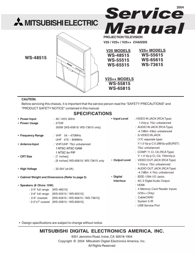
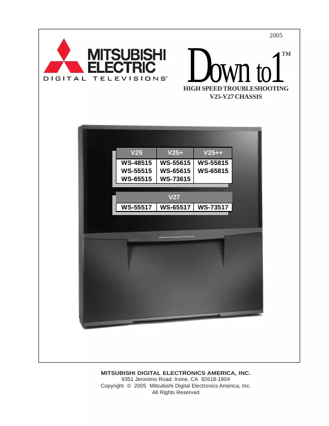
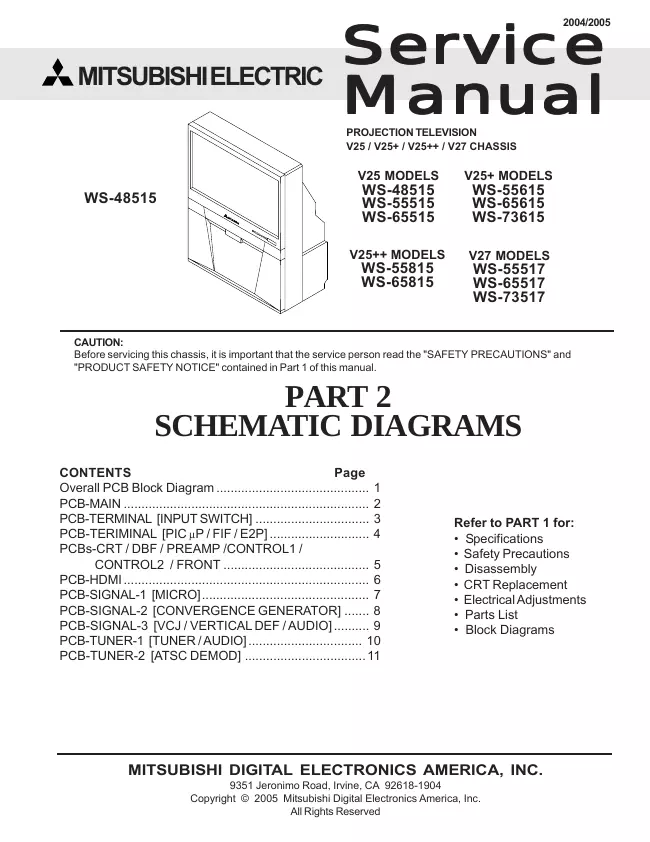
Mitsubishi - WS-65815 - TV
Manufacturer:
Equipment:
WS-65815
Date:
2004
Category:
Group:
Sub Group:

3 Manuals

Service manual
Manual type:
Service manual
Pages:
81
Size:
1.5 MB
Language:
english
Revision:
Manual-ID:
Date:
Quality:
Electronic document, no scan, very well readable.
Upload date:
Jan. 24, 2009
MD5:
0539bf9e-be26-1cfb-7fd4-ae84d625ebdf
Downloads:
7421

Information

This service manual provides service instructions for the V25, V25+ and V25++ PTV chassis types. The specific models for each chassis type are listed below. Service personnel should read this manual thoroughly before servicing these chassis. V25 Chassis V25+ Chassis V25++ Chassis WS-48515 WS-55615 WS-55815 WS-55515 WS-65615 WS-65815 WS-65515 WS-73615 This service manual includes: 1. Assembly and disassembly instructions for the front and rear cabinet components. 2. Servicing of the Lenticular Screen and Fresnel Lens. 3. Servicing printed circuit boards (PCBs). 4. CRT replacement procedure. 5. Electrical adjustments. 6. Chip parts replacement procedures. 7. Circuit path diagrams. The parts list section of this service manual includes: 1. Electrical parts. 2. Cabinet and screen parts. Schematic and block diagrams of the above listed models are included in this service manual for better under- standing of the circuitry. PCB drawings are also included for easy location of parts and test points.

show more

Service manual
Manual type:
Service manual
Pages:
12
Size:
278.9 KB
Language:
english
Revision:
Manual-ID:
Date:
Quality:
Electronic document, no scan, very well readable.
Upload date:
Feb. 11, 2009
MD5:
689266ec-2c0c-51e2-e30d-5a759ef35c34
Downloads:
8459

Information

High Speed Troubleshooting Safety Precautions ......................................................................................................................... 2 Cabinet Disassembly ...................................................................................................................... 3 Chassis Removal ............................................................................................................................ 5 Troubleshooting .............................................................................................................................. 6 PCB Locations and Functions......................................................................................................... 8 PCB Parts Reference ...................................................................................................................... 9

show more

Service manual with schematics
Manual type:
Service manual with schematics
Pages:
12
Size:
15.1 MB
Language:
english
Revision:
Manual-ID:
Date:
Quality:
Electronic document, no scan, very well readable.
Upload date:
Jan. 3, 2012
MD5:
d5312e2f-cda2-7fbc-3cfd-8cdc90d6e5f5
Downloads:
10303

Information

Before servicing this chassis, it is important that the service person read the SAFETY PRECAUTIONS and PRODUCT SAFETY NOTICE contained in Part 1 of this manual. PART 2 SCHEMATIC DIAGRAMS CONTENTS Page Overall PCB Block Diagram ........................................... 1 PCB-MAIN ..................................................................... 2 PCB-TERMINAL [INPUT SWITCH] ................................ 3 PCB-TERIMINAL [PIC μP / FIF / E2P] ............................ 4 PCBs-CRT / DBF / PREAMP /CONTROL1 / CONTROL2 / FRONT ......................................... 5 PCB-HDMI..................................................................... 6 PCB-SIGNAL-1 [MICRO]............................................... 7 PCB-SIGNAL-2 [CONVERGENCE GENERATOR] ....... 8 PCB-SIGNAL-3 [VCJ / VERTICAL DEF / AUDIO].......... 9 PCB-TUNER-1 [TUNER / AUDIO]................................ 10 PCB-TUNER-2 [ATSC DEMOD] ..................................11 Refer to PART 1 for: • Specifications • Safety Precautions • Disassembly • CRT Replacement • Electrical Adjustments • Parts List • Block Diagrams

show more