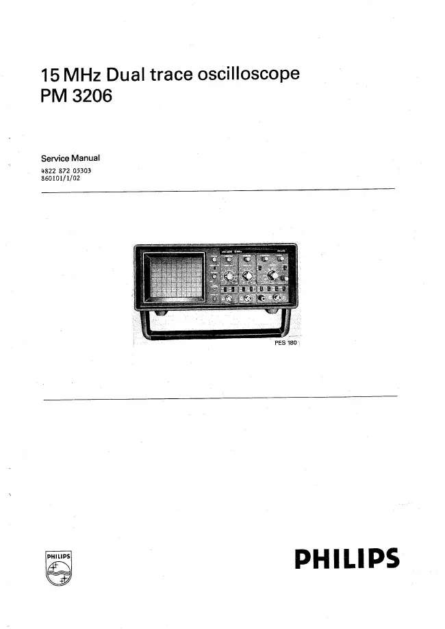
Philips - PM 3206 - Oscilloscope
Manufacturer:
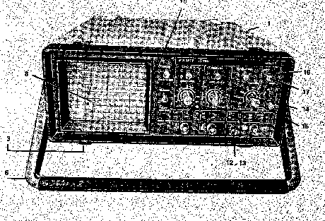
Image 1 of 2
If you have any other photos or manuals for the
Philips PM 3206
you can
upload the files here.
Equipment:
PM 3206
Date:
1986
Category:
Group:
Sub Group:
Information
1 Manual
Service manual
Manual type:
Service manual
Pages:
134
Size:
13.0 MB
Language:
english
Revision:
Manual-ID:
4822 872 05303
Date:
January 1986
Quality:
Scanned document, all readable.
Upload date:
July 31, 2020
MD5:
e969e412-b523-186e-c8b1-e285ec07aaf7
Downloads:
445