Pioneer - CT-F2121 - Cassette deck
Manufacturer:
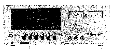
Image 1 of 3
If you have any other photos or manuals for the
Pioneer CT-F2121
you can
upload the files here.
Equipment:
CT-F2121
Date:
Category:
Group:
Sub Group:
Information
Systems......................Compact cassette, 2-channel stereo
Recording .... AC bias system (bias frequency: 85kHz)
Erasing.............................................AC
push-pull system
Heads . . ."Permalloy Solid" recording/playback headx 1
Ferritte erasing head x 1
Motor.................... Electronically-controlled DC motor
Fast Winding Time............... Approximately 80 seconds
(C-60 tape)
Wow and Flutter...............No more than 0.12% (WRMS)
Frequency Response.........................Standard, LH tapes;
30 to 13,000Hz (40 to 11,000Hz, ±3dB) Chromium dioxide tape;
30 to 16,000Hz (40 to 12,000Hz, ±3dB)
Signal-to-Noise Ratio...........................Dolby OFF; 48dB
(standard and LH tapes) Dolby ON; 58dB (over 5kHz, standard
and LH tapes) (When chromium dioxide tape is used,
signal-to-noise ratio is further improved by 4.5dB over 5kHz)
Inputs (Sensitivity/Maximum allowable input/lmpedance) MIC x
2; 0.3mV/63mV/20kß, 6mm<£> jacks (Reference Mic impedance;
600Ω to 20k£2) LINE x 2; 63mV/12V/50ka, Pin jacks REC/PB x
1; 10mV/2V/10ktt, 5P jack
(DIN standard)
Outputs (Reference level/Load impedance)
LINE x 2; 450mV/50ki2, Pin jacks HEADPHONE x 1; 80mV/8£2,
6mm0, stereo jack REC/PB x 1; 450mV/50k£2, 5P jack
(DIN standard)
Semiconductors..........Amplifier section; 41 transistors
(including 2 FETs) 28 diodes (including 3 zener diodes, 1
LED) Motor control section; 2 transistors, 1 diode
Subfunctions.........................«Dolby system (ON OFF)
with indicator lamp •Tape selector (STD/Cr02) Independently
switchable bias and equalizer •Full-auto stop mechanism (in
all modes of PLAY/REC/FF/REW) •Cassette compartment
illumination Power Requirements .... AC120V, 60Hz (KCU model)
AC220V, 50/60Hz (NB model) AC 120V, 220V and 240V
(switchable) 50-60Hz
(DV, DP model)
Power Consumption........................... 15 watts (max.)
Dimensions ................. 350(W) x 142(H) x 282(D) mm.
13-3/4(W) x 5-5/8(H) x 11-1/8 in.
Weight ..................14 lb 9 oz (6.6 kg) (without package)
Accessories...................................Stereo
connecting cord
with pin plugs x 2 Head cleaning kit x 1 Operating
instructions x 1
1 Manual
Service manual
Manual type:
Service manual
Pages:
60
Size:
15.7 MB
Language:
english
Revision:
Manual-ID:
ART-144-0
Date:
Quality:
Scanned document, all readable.
Upload date:
Sept. 27, 2015
MD5:
f9cff7a2-5f7f-58d1-8452-b3e71a7c84b8
Downloads:
869