Pioneer - FX-MG9106ZT-91/ES - Car Radio
Manufacturer:
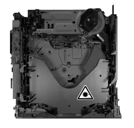
Image 1 of 1
If you have any other photos or manuals for the
Pioneer FX-MG9106ZT-91/ES
you can
upload the files here.
Equipment:
FX-MG9106ZT-91/ES
Date:
2000
Category:
Group:
Sub Group:
Information
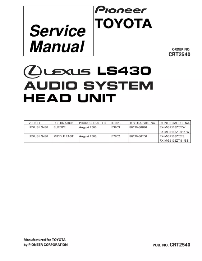
LEXUS LS430 AUDIO SYSTEM HEAD UNIT
Power
source...............................................13.2V±0.1V
DC
Electrode dark current
.....................................2mA or less
Grounding
system........................................Negative type
Dimensions(Chassis)..............178(W)x100(H)x166(D)mm
(Grille) ....................261(W)x165(H)x44(D)mm
Weight...............................................................2.98±0.12kg
Cassette player
Tape................................Compact cassette
tape(C30-C90)
Tape speed ......4.76 cm/sec.(+0.14 cm/sec.,-0.05 cm/sec.)
Wow and flutter.................................0.2% or
less(WRMS)
Crosstalk
..........................................................40dB
or less
Stereo
Separation.........................................30dB or more
S/N
.................................................................41dB
or more
Distortion.............................................................3%
or less
CD player
System ...................................Compact disc audio
system
Usable discs
..................................................Compact disc
Signal format .....................Sampling frequency : 44.1kHz
.....................................Number of guantization
: 16;linear
S/N
.................................................................70dB
or more
Distortion..........................................................0.2%
or less
1 Manual
Service manual
Manual type:
Service manual
Pages:
100
Size:
8.7 MB
Language:
english
Revision:
Manual-ID:
CRT2540
Date:
Quality:
Electronic document, no scan, very well readable.
Upload date:
May 18, 2014
MD5:
0cb76e6c-db9b-df88-37e0-53c64ec30e50
Downloads:
1661