Quadtech Inc. - Sentry 10 Plus - Analyzer
Manufacturer:
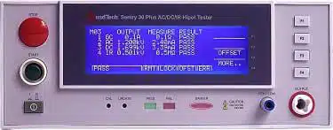
Image 1 of 1
If you have any other photos or manuals for the
Quadtech Inc. Sentry 10 Plus
you can
upload the files here.
Equipment:
Sentry 10 Plus
Date:
2005
Category:
Group:
Sub Group:
Information
The Sentry Plus Series is available in three models, the 10,
20 and 30, all of which provide AC
Hipot testing capability. Additionally, the Sentry 20 & 30
Plus instruments provide DC Hipot
testing. The Sentry 30 Plus unit provides Insulation
Resistance testing. The hipot test can be
programmed over a voltage range of 0.05 to 5kV AC and 0.05
to 6kV DC with a min/max
leakage current detection range of 0.001 to 20mA AC and
0.0001 to 5mA DC. Insulation
resistance measurements are possible to 50GΩ at programmable
DC test voltages between 50
and 1000V. Each instrument comes standard with programmable
ground continuity, internal
storage containing 60 memory locations (10 steps each) and a
remote interface with start/stop
inputs & pass/fail outputs.
UL Requirements
The Sentry Plus Series instruments meet the requirements
outlined by UL for Hipot Testers. The
Sentry Plus indicates the test potential (test voltage), has
both visual and audible indication of
failure and the STOP switch must be manually pressed prior
to another measurement being
made. The Sentry Plus Series instrument has a 100VA output
[(5000V * 20mA) = 100VA]. The
Sentry Plus Series instrument also measures and displays the
output voltage directly at the output
terminals during the test.
1 Manual
User manual
Manual type:
User manual
Pages:
85
Size:
360.0 KB
Language:
english
Revision:
Manual-ID:
150697/A4
Date:
January 2005
Quality:
Electronic document, no scan, very well readable.
Upload date:
Jan. 29, 2017
MD5:
528365f7-0535-7bff-c44a-d0435fbd65d6
Downloads:
2144