Sanyo - CM1812 - Air Conditioner
Manufacturer:
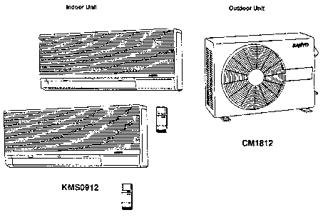
Image 1 of 1
If you have any other photos or manuals for the
Sanyo CM1812
you can
upload the files here.
Equipment:
CM1812
Date:
Category:
Group:
Sub Group:
Information
2 Manuals
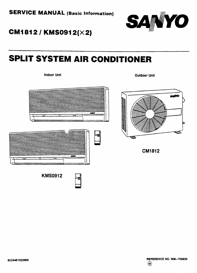
Service manual
Manual type:
Service manual
Pages:
15
Size:
792.0 KB
Language:
english
Revision:
Manual-ID:
8526481022500
Date:
Quality:
Scanned document, all readable.
Upload date:
Dec. 10, 2013
MD5:
ea24ef1f-7c81-a164-c2a1-82cf3fdc6877
Downloads:
1138
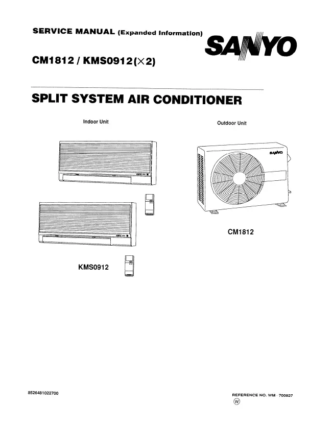
Service manual
Manual type:
Service manual
Pages:
33
Size:
2.6 MB
Language:
english
Revision:
Manual-ID:
W M -7 0 0 8 2 7
Date:
Quality:
Scanned document, all readable.
Upload date:
Dec. 21, 2016
MD5:
a56fa4ba-741d-ec72-3e64-713a03ce7df4
Downloads:
734