Sony - CCD-TR713E - Video camera
Manufacturer:
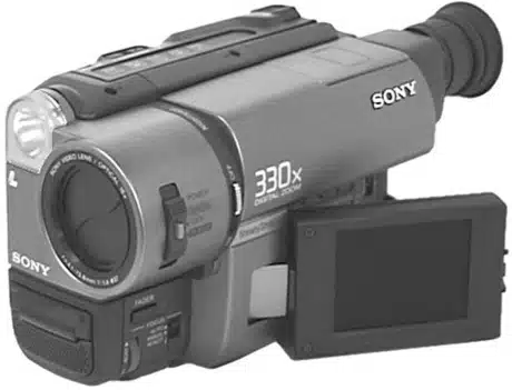
Image 1 of 2
If you have any other photos or manuals for the
Sony CCD-TR713E
you can
upload the files here.
Equipment:
CCD-TR713E
Date:
1999
Category:
Group:
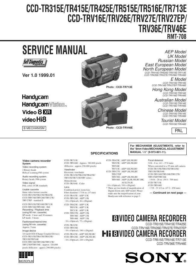
Sub Group:
Information
Video camera recorder
System
Video recording system
2 Rotary heads
Helical scanning FM system
Audio recording system
Rotary heads, FM system
Video signal
PAL color, CCIR standards
Usable cassette
8mm video format cassette
CCD-TR315E/TR415E/TR425E
CCD-TRV16E/TRV26E/TRV27E/
TRV27EP : standard 8
CCD-TR515E/TR516E/TR713E
CCD-TRV36E/TRV46E : Hi8
Recording / Playback time
(using 90 min. cassette)
SP mode: 1 hour and 30 minutes
LP mode: 3 hours
Fastforward/rewind time
(using 90 min. cassette)
Approx. 5 min.
Image device
1/4 inch CCD (Charge Coupled Device)
CCD-TR315E/TR415E/TR425E/
TR515E/TR516E
CCD-TRV16E/TRV26E/TRV27E/
TRV27EP/TRV36E : Approx. 320,000
pixels (Effective : approx 290,000 pixels)
CCD-TR713E
CCD-TRV46E : Approx. 380,000 pixels
(Effective : approx 230,000 pixels)
Viewfinder
Electronic viewfinder
CCD-TR315E/TR415E/TR425E/
TR515E/TR713E/TRV series :
Monochrome
CCD-TR516E : Color
Lens
Combined power zoom lens
Filter diameter 1 7/16 in. (37 mm)
CCD-TR415E : AEP*,UK
CCD-TRV26E : AEP*,UK
: 18 x (Optical), 36 x (Digital)
CCD-TR425E : AEP*,UK
TR515E : AEP*,UK
TR713E : AEP*,UK
CCD-TRV27E : AEP*,UK
TRV36E : AEP*,UK
TRV46E : AEP*,UK
: 18 x (Optical), 72 x (Digital)
CCD-TR315E
CCD-TRV16E
: 18 x (Optical), 180 x (Digital)
CCD-TR415E : AEP*,EE,NE.RU
CCD-TRV26E : AEP*,EE,NE.RU
: 18 x (Optical), 220 x (Digital)
CCD-TR425E : AEP*,EE,NE,RU
TR515E : AEP*,EE,NE,RU
TR516E
TR713E : AEP*,EE,NE,RU
CCD-TRV27E : AEP*,EE,NE,RU
TRV27EP
TRV36E : AEP*,EE,NE,RU
TRV46E : AEP*,E,EE,NE,RU,HK,
AUS,CN,JE
: 18 x (Optical), 330 x (Digital)
* There are two kinds of magnification of
Digital Zoom only AEP model. Please
make sure the magnification of your
Handycam with reference to page 3.
Focal distance
3/16 - 8 in. (4.1 - 37.8 mm)
When converted to a 35 mm still camera
CCD-TR315E/TR415E/TR425E/
TR515E/TR516E
CCD-TRV16E/TRV26E/TRV27E/
TRV27EP/TRV36E
: 1 9/16 - 28 in. (39.4 - 709 mm)
CCD-TR713E
CCD-TRV46E
: 1 7/8 - 33 1/2 in. (47.2 - 850 mm)
Color temperature
Auto
Minimum illumination*
0.4 lux at F 1.4
0 lux (in NightShot mode)**
Illumination range
0.4 lux to 100,000 lux
Recommended illumination
More than 100 lux
* Minimum illumination expresses the
light level a camcorder requires to
produce a picture. Visible minimum
low light expresses the light level to
produce a visible signal.
**Object invisible for the dark can be
shot with infrared lighting.
LCD screen (TRV series only)
Picture
2.5 inches measured diagonally
2 x 1 1/2 in.(50.3 x 37.4 mm)
On-screen display
TN LCD/TFT active matrix method
Total dot number
61,380 (279 x 220)
Input and output connectors
Video output
Phono jack, 1 Vp-p, 75 ohms, unbalanced
Audio output
Monaural, Phone jack, 327 mV
(at output impedance 47 kilohms)
impedance less than 2.2 kilohms
RFU DC OUT
Special minijack, DC 5V
Earphone jack (TRV series only)
Monaural minijack (ø 3.5 mm)
LANC control jack
Stereo mini-minijack (ø 2.5 mm)
MIC jack
Mini jack, 0.388mV low impedance with
2.5 to 3.0 V DC, output impedance 6.8
kilohms (ø 3.5 mm) : Monaural type
Speaker (TRV series only)
Dynamic speaker
General
Power requirements
7.2 V (battery pack)
8.4 V (AC power adaptor)
Average power consumption
(when using the battery pack)
During camera recording
CCD-TR516E : 2.4 W
CCD-TR315E/TR415E/TR425E/
TR515E : 2.5 W
CCD-TR713E : 2.6 W
During camera recording using
LCD
CCD-TRV16E/TRV26E/TRV27E/
TRV27EP/TRV36E : 3.1 W
CCD-TRV46E : 3.2 W
Viewfinder
CCD-TRV16E/TRV26E/TRV27E/
TRV27EP/TRV36E : 2.5 W
CCD-TRV46E : 2.6 W
Operating temperature
32°FC to 104°F (C0°C to 40°C)
Storage temperature
-4°FC to 140°F (-20°C to +60°C)
Dimensions (Approx.)
4 1/4 x 4 1/4 x 7 5/8 in.
107 x 107 x 193 mm)(w/h/d)
Mass (Approx.)
CCD-TR516E : 1 lb 11 oz (780 g)
CCD-TR315E : 1 lb 11 oz (790 g)
CCD-TR415E/TR425E/TR515E :
1 lb 12 oz (810 g)
CCD-TR713E : 1 lb 12 oz (820 g)
CCD-TRV16E/TRV27EP : 1 lb 14 oz (870 g)
CCD-TRV46E ; E,HK,AUS,CN,JE :
1 lb 15 oz (880 g)
CCD-TRV26E/TRV27E/TRV36E :
1 lb 15 oz (890 g)
CCD-TRV46E ;AEP,UK,EE,NE,RU :
1 lb 15 oz (900 g)
excluding the battery pack, lithium
battery, cassette and shoulder strap
2 lb 3 oz (1 kg) (TRV series)
CCD-TR516E : 2 lb 1 oz (920g)
CCD-TR315E : 2 lb 1 oz (930g)
CCD-TR415E/TR425E/TR515E :
2 lb 1 oz (950g)
CCD-TR713E : 2 lb 1 oz (960g)
including the battery pack NP-F330,
lithium battery CR2025, cassette and
shoulder strap
Microphone
Monaural type
Supplied accessories
See page 4.
AC power adaptor
Power requirements
100 -240 V AC, 50/60 Hz
Power consumption
23 W
Output voltage
DC OUT: 8.4 V, 1.5 A in operating mode
Operating temperature
32°F to 104°F(0°C to 40°C)
Storage temperature
-4°F to +140°F(-20°C to +60°C)
Dimensions (Approx.)
5 x 1 9/16 x 2 1/2 in. (125 x 39 x 62
mm)(w/h/d) excluding projecting parts
Mass (Approx.)
9.8 oz (280 g) excluding power cord
1 Manual
Service manual
Manual type:
Service manual
Pages:
181
Size:
19.1 MB
Language:
english
Revision:
Manual-ID:
9-974-129-11
Date:
January 1999
Quality:
Electronic document, no scan, very well readable.
Upload date:
Jan. 28, 2017
MD5:
2e22ec07-86a7-1b54-6b8d-405dcca819a1
Downloads:
6322