
.....obsolete user manuals, a lot of repair manuals, free service manuals, rare schematic diagrams, usefull service instructions, pdf books, how to repair instructions, lost operating manuals, old handbooks, tons of part lists, hidden service bulletins, your instruction books, informative repair tips, complete disassembly routines.....


What are you looking for?


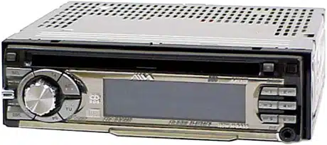
Sony - CDC-X30MP - Car CD Tuner
Manufacturer:
Equipment:
CDC-X30MP
Date:
2003
Category:
Group:
Sub Group:

Information

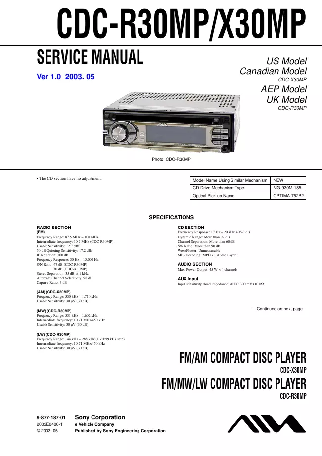
RADIO SECTION (FM) Frequency Range: 87.5 MHz – 108 MHz Intermediate frequency: 10.7 MHz CDC-R30MP Usable Sensitivity: 12.7 dBf 50 dB Quieting Sensitivity: 17.2 dBf IF Rejection: 100 dB Frequency Response: 30 Hz – 15,000 Hz S/N Ratio: 67 dB CDC-R30MP 70 dB CDC-X30MP Stereo Separation: 35 dB at 1 kHz Alternate Channel Selectivity: 98 dB Capture Ratio: 3 dB (AM) CDC-X30MP Frequency Range: 530 kHz – 1,710 kHz Usable Sensitivity: 30 μV (30 dB) (MW) CDC-R30MP Frequency Range: 531 kHz – 1,602 kHz Intermediate frequency: 10.71 MHz/450 kHz Usable Sensitivity: 30 μV (30 dB) (LW) CDC-R30MP Frequency Range: 144 kHz – 288 kHz (1 kHz/9 kHz step) Intermediate frequency: 10.71 MHz/450 kHz Usable Sensitivity: 30 μV (30 dB) CD SECTION Frequency Response: 17 Hz – 20 kHz +0/–3 dB Dynamic Range: More than 92 dB Channel Separation: More than 60 dB S/N Ratio: More than 90 dB Wow/Flutter: Unmeasurable MP3 Decoding: MPEG 1 Audio Layer 3 AUDIO SECTION Max. Power Output: 45 W × 4 channels AUX Input Input sensitivity (load impedance) AUX: 300 mV (10 kΩ)

show more

1 Manual

Service manual
Manual type:
Service manual
Pages:
52
Size:
4.7 MB
Language:
english
Revision:
1.0
Manual-ID:
9-877-187-01
Date:
Quality:
Electronic document, no scan, very well readable.
Upload date:
April 6, 2012
MD5:
f1eeda4d-71d1-0152-dc47-c6749e060b0c
Downloads:
1758
Last month downloads:
8

Information

TABLE OF CONTENTS 1. GENERAL Connections CDC-X30MP 4 Connections CDC-R30MP 5 2. DISASSEMBLY 2-1. Sub Panel Assy ... 8 2-2 CD mechanism Block ... 8 2-3. Main Board Section ... 9 2-4. Main Board ... 9 2-5. Heat Sink (CT) ... 10 2-6. Sub Board ... 10 2-7. Servo Board ... 11 2-8. Floating Block Assy ... 11 2-9. Lever Assy (CD Up Holder CNF) ... 12 2-10. Lever (CD Roller) Sub Assy ... 12 2-11. Lever Assy (CD Holder) ... 13 2-12. Motor (Sled) Sub Assy ... 13 2-13. Pick-up Sub Assy ... 14 3. ELECTRICAL ADJUSTMENT... 15 4. DIAGRAMS 4-1. IC Pin Descriptions ... 16 4-2. Block Diagram –CD Section– ... 23 4-3. Block Diagram –Main Section– ... 24 4-4. Block Diagram –Front Section–... 25 4-5. Circuit Boards Location ... 25 4-6. Printed Wiring Boards –CD Mechanism Section– ... 26 4-7. Schematic Diagram –CD Mechanism Section (1/2)– ... 28 4-8. Schematic Diagram –CD Mechanism Section (2/2)– ... 29 4-9. Printed Wiring Board –Main Section– ... 30 4-10. Schematic Diagram –Main Section (1/2)– ... 31 4-11. Schematic Diagram –Main Section (2/2)– ... 32 4-12. Printed Wiring Boards –Front Section– ... 33 4-13. Schematic Diagram –Front Section– ... 34 4-14. IC Block Diagrams ... 35 5. EXPLODED VIEWS 5-1. Chassis Section ... 38 5-2. Front panel Section ... 39 5-3 CD mechanism ection (1) ... 40 5-4 CD mechanism ection (2) ... 41 6. ELECTRICAL PARTS LIST ... 42

show more