Sony - CDX-L580X - Car CD Tuner
Manufacturer:
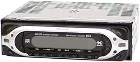
Image 1 of 1
If you have any other photos or manuals for the
Sony CDX-L580X
you can
upload the files here.
Equipment:
CDX-L580X
Date:
2002
Category:
Group:
Sub Group:
Information
CD player section
Signal-to-noise ratio 90 dB
Frequency response 10 – 20,000 Hz
Wow and flutter Below measurable limit
Tuner section
FM
Tuning range 87.5 – 108.0 MHz
Aerial terminal External aerial connector
Intermediate frequency 10.7 MHz/450 kHz
Usable sensitivity 9 dBf
Selectivity 75 dB at 400 kHz
Signal-to-noise ratio 67 dB (stereo),
69 dB (mono)
Harmonic distortion at 1 kHz
0.5% (stereo),
0.3% (mono)
Separation 35 dB at 1 kHz
Frequency response 30 – 15,000 Hz
MW/LW
Tuning range MW: 531 – 1,602 kHz
LW: 153 – 279 kHz
Aerial terminal External aerial connector
Intermediate frequency 10.7 MHz/450 kHz
Sensitivity MW: 30 μV
LW: 40 μV
Power amplifier section
Outputs Speaker outputs
(sure seal connectors)
Speaker impedance 4 – 8 ohms
Maximum power output 50 W × 4 (at 4 ohms)
General
Outputs Audio outputs (front)
(CDX-CA680X only)
Audio outputs (rear)
Power aerial relay control
terminal
Power amplifier control
terminal
Inputs Telephone ATT control
terminal
Remote controller input
terminal
BUS control input terminal
(CDX-CA680X only)
BUS audio input terminal
(CDX-CA680X only)
Tone controls Low ±10 dB at 60 Hz
(XPLOD)
Mid ±10 dB at 1 kHz
(XPLOD)
High ±10 dB at 10 kHz
(XPLOD)
Power requirements 12 V DC car battery
(negative ground)
Dimensions Approx. 178 × 50 × 180 mm
(w/h/d)
Mounting dimension Approx. 182 × 53 × 161 mm
(w/h/d)
Mass Approx. 1.2 kg
Supplied accessories Parts for installation and
connections
Front panel case (1)
1 Manual
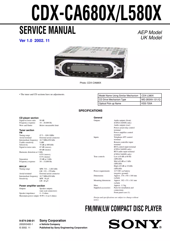
Service manual
Manual type:
Service manual
Pages:
40
Size:
5.2 MB
Language:
english
Revision:
1.0
Manual-ID:
9-874-248-01
Date:
Quality:
Electronic document, no scan, very well readable.
Upload date:
April 6, 2012
MD5:
f0ce61bd-3458-1a7c-528f-1590924ed1cd
Downloads:
1817