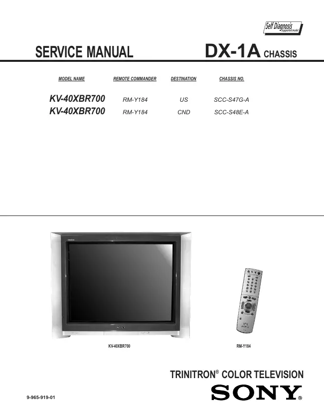
Sony - DX-1A - TV
Manufacturer:
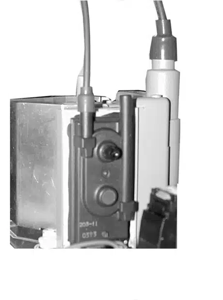
Image 1 of 11
If you have any other photos or manuals for the
Sony DX-1A
you can
upload the files here.
Equipment:
DX-1A
Date:
Category:
Group:
Sub Group:
Information
1 Manual
Service manual
Manual type:
Service manual
Pages:
205
Size:
21.0 MB
Language:
english
Revision:
Manual-ID:
9-965-919-01
Date:
Quality:
Electronic document, no scan, very well readable.
Upload date:
Dec. 30, 2018
MD5:
6d7c6338-6a16-dac5-af35-983c136be942
Downloads:
866