Sony - KDL-46SL140 - TV
Manufacturer:
Image 1 of 26
If you have any other photos or manuals for the
Sony KDL-46SL140
you can
upload the files here.
Equipment:
KDL-46SL140
Date:
2008
Category:
Group:
Sub Group:
Information
3 Manuals
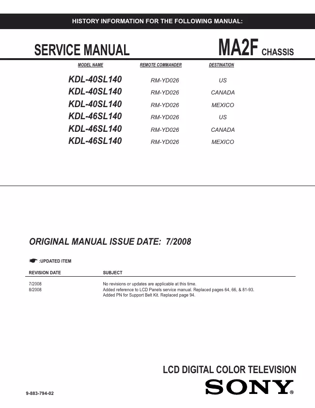
Service manual
Manual type:
Service manual
Pages:
96
Size:
15.8 MB
Language:
english
Revision:
Manual-ID:
9-883-794-02
Date:
August 2008
Quality:
Electronic document, no scan, very well readable.
Upload date:
Sept. 23, 2018
MD5:
858833af-54cc-53cc-14fd-78712159d3d4
Downloads:
1689
Service manual
Manual type:
Service manual
Pages:
96
Size:
15.8 MB
Language:
english
Revision:
Manual-ID:
9-883-794-02
Date:
August 2008
Quality:
Electronic document, no scan, very well readable.
Upload date:
Sept. 23, 2018
MD5:
858833af-54cc-53cc-14fd-78712159d3d4
Downloads:
1689
Service manual
Manual type:
Service manual
Pages:
96
Size:
15.8 MB
Language:
english
Revision:
Manual-ID:
9-883-794-02
Date:
August 2008
Quality:
Electronic document, no scan, very well readable.
Upload date:
Sept. 23, 2018
MD5:
858833af-54cc-53cc-14fd-78712159d3d4
Downloads:
1689