Sony - KV-27FS100 - TV
Manufacturer:

Image 1 of 6
If you have any other photos or manuals for the
Sony KV-27FS100
you can
upload the files here.
Equipment:
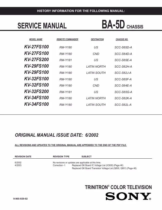
KV-27FS100
Date:
2003
Category:
Group:
Sub Group:
Information
Introducing the FD Trinitron WEGA ® Features
Some of the features you will enjoy include:
FD Trinitron Flat CRT — Technologically advanced tube
delivers a picture with uncompromising
accuracy and outstanding image detail.
Y, PB , P R Inputs — A component video input connection for
a superior picture quality
(480i only).
Surround — Simulates theater quality sound for stereo programs.
Parental Control (V-Chip) — A tool to help parents monitor
what their children watch on TV by
establishing rating limits.
Picture in Picture (PIP) — Allows you to view two programs
simultaneously
(KV-27FS200, KV-32FS200, KV-36FS200 only).
Favorite Channels — Instant access to your favorite channels
with the touch of a button.
Info Banner — A new, convenient feature that displays the
name and the remaining time of the
current program viewed, if available.
Universal Remote Control — Program your remote control to
operate your connected cable box,
VCR, digital satellite receiver, or DVD player.
Energy Star® — Meets the Energy Star guidelines for energy
efficiency.
Front Panel Controls — Allows access to the on-screen menus
without the use of a remote
control.
Front A/V Inputs — A quick connection for video games,
camcorders or stereo/mono equipment.
2 Manuals
Service and user manual
Manual type:
Service and user manual
Pages:
254
Size:
8.8 MB
Language:
english, french, italian
Revision:
Manual-ID:
9-965-929-02
Date:
April 2003
Quality:
Electronic document, no scan, very well readable.
Upload date:
Sept. 29, 2018
MD5:
d45436fb-e500-e8ed-17a2-8009633c6347
Downloads:
2286
Service manual
Manual type:
Service manual
Pages:
252
Size:
8.8 MB
Language:
english
Revision:
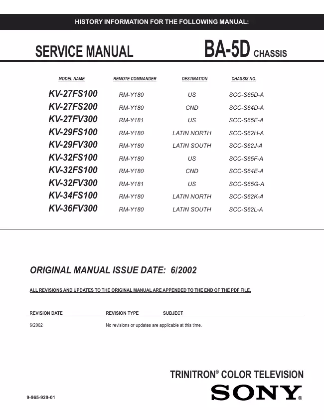
Manual-ID:
9-965-929-01
Date:
June 2002
Quality:
Electronic document, no scan, very well readable.
Upload date:
Oct. 3, 2018
MD5:
0738d33a-ce8d-7078-a051-28724c778dcd
Downloads:
3287