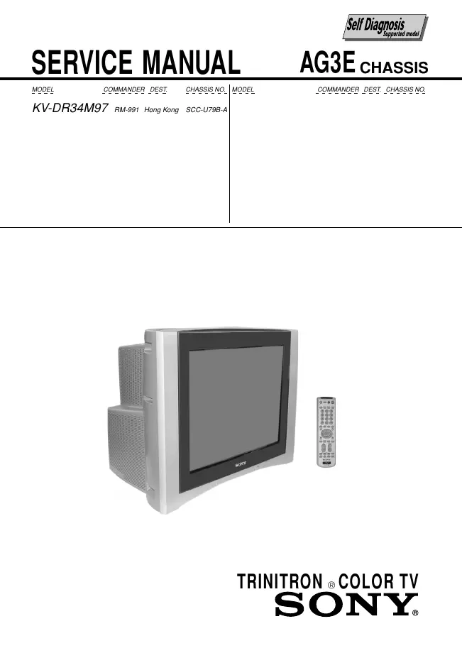
Sony - KV-DR34M97 - TV
Manufacturer:
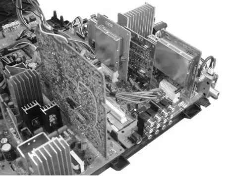
Image 1 of 17
If you have any other photos or manuals for the
Sony KV-DR34M97
you can
upload the files here.
Equipment:
KV-DR34M97
Date:
Category:
Group:
Sub Group:
Information
1 Manual
Service manual
Manual type:
Service manual
Pages:
149
Size:
17.8 MB
Language:
english
Revision:
Manual-ID:
Date:
Quality:
Electronic document, no scan, very well readable.
Upload date:
Dec. 30, 2018
MD5:
581c6a77-f558-596e-d813-282eb923cf8d
Downloads:
836