Tektronix - DF 1 - Analyzer
Manufacturer:
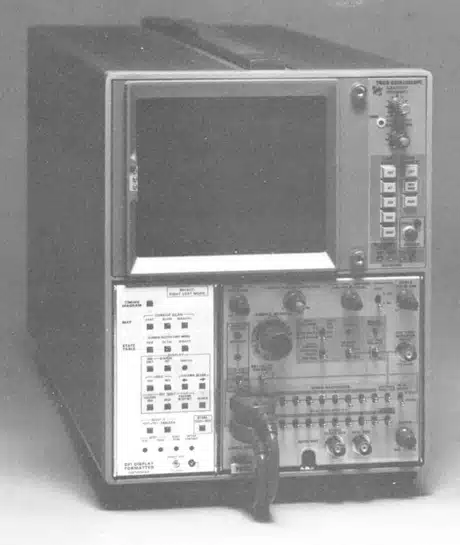
Image 1 of 1
If you have any other photos or manuals for the
Tektronix DF 1
you can
upload the files here.
Equipment:
DF 1
Date:
1976
Category:
Group:
Sub Group:
Information
The DF1 Display Formatter provides data-domain display modes
in addition to the existing time-domain display of the 7D01
Logic Analyzer.
It adds state table displays with a comparison mode, and a
map display. The DF1 attaches to the left side of the 7D01,
forming a three-wide plug-in assembly. This assembly
operates in a 7000-series oscilloscope mainframe to comprise
a complete 16-channel logic timing-state analyzer system.
A microprocessor controlled memory system, contained in the
DF1, is capable of recording two 7D01 information records.
Portions of both information records may be displayed
concurrently in a state table presentation.
State tables are displayed in terms of either hexadecimal,
octal, or binary formats. This data may be displayed in up
to two tables of 17 lines of 16-bit words each. The
left-hand table displays data currently stored in the 7D01
memory (7D01 display). The right-hand table displays data
that has been transferred from previous 7D01 displays to the
DF1 memory (reference display). The DF1 compares the 2
tables and resets the 7D01 when the 7D01 data equals the
reference data.
The map function plots a dot display of the 16 data channels
in X-Y coordinate points. Each dot location represents one
possible combination of up to 16 inputs to the 7D01
1 Manual
Service and user manual
Manual type:
Service and user manual
Pages:
111
Size:
36.1 MB
Language:
english
Revision:
First Edition
Manual-ID:
070-2150-00
Date:
December 1976
Quality:
Scanned document, all readable.
Upload date:
Dec. 30, 2017
MD5:
267c3cae-af4c-f378-f126-de43a6080e96
Downloads:
559