Tektronix - R7603 - Oscilloscope
Manufacturer:
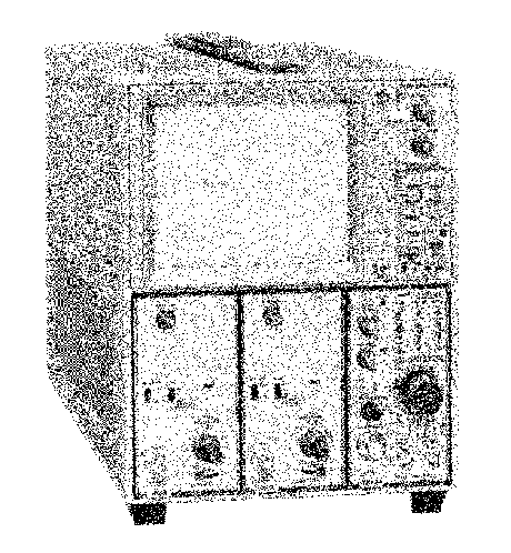
Image 1 of 2
If you have any other photos or manuals for the
Tektronix R7603
you can
upload the files here.
Equipment:
R7603
Date:
1972
Category:
Group:
Sub Group:
Information
7603 Features
The TEKTRONIX 7603 Oscilloscope is a solid state, light
weight instrument designed for general-purpose measuring
applications. This instrument has three plug-in compartments
that accept TEKTRONIX 7-series plug-in units to form a
complete measurement system. The two plug-in compartments
on the left are connected to the vertical deflection
system. The right plug-in compartment is connected to the
horizontal deflection system. Electronic switching
between the vertical plug-in compartments allows a
multi-trace vertical display. The flexibility of this
plug-in feature and the variety of plug-in units available
allow this system to be used for many measurement
applications. In addition, the instrument contains
a readout system to provide a CRT display of alphanumeric
information from the plug-in units. Data such as deflection
factor sweep rate, etc. can be encoded and displayed on
the CRT. '
This instrument features a large-screen, 8 X 10 division
display; each division equals 1.22 centimeters. The
CRT provides small spot size and fast writing speed.
Regulated DC power supplies assure that performance
is not affected by variations in line voltage and frequency,
or by changes in the load due to the varying power
requirements of the plug-in units Maximum power consumption
is about 170 watts (60 hertz, 115-volt line).
2 Manuals
Service manual
Manual type:
Service manual
Pages:
211
Size:
35.4 MB
Language:
english
Revision:
B
Manual-ID:
070-1429-00
Date:
Quality:
Scanned document, all readable.
Upload date:
Jan. 21, 2009
MD5:
915e7902-33e6-2bbc-eb1b-77b020cfeee5
Downloads:
4967
Service and user manual
Manual type:
Service and user manual
Pages:
250
Size:
50.0 MB
Language:
english
Revision:
Revised
Manual-ID:
070-1429-00
Date:
Quality:
Scanned document, all readable.
Upload date:
April 26, 2013
MD5:
93bdd2ce-aae0-8d9f-3f7b-91eaebec0eb4
Downloads:
2424