Tektronix - SW503 - Generator
Manufacturer:
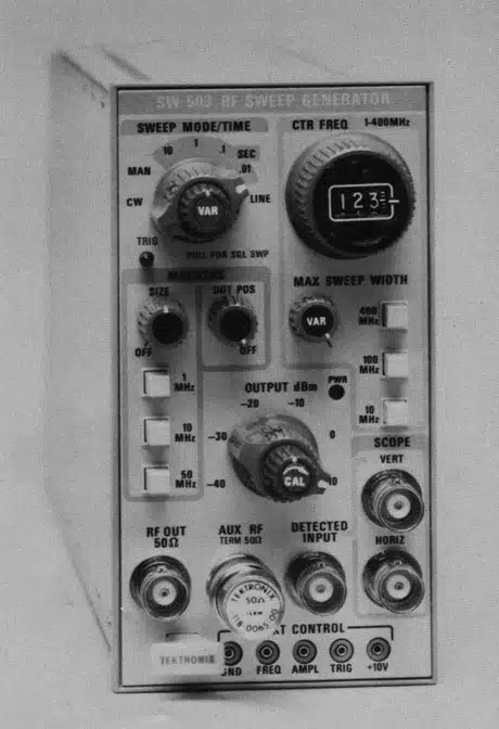
Image 1 of 1
If you have any other photos or manuals for the
Tektronix SW503
you can
upload the files here.
Equipment:
SW503
Date:
1977
Category:
Group:
Sub Group:
Information
The SW 503 is a TM 500-Series plug-in that provides a swept
frequency of 1 MHz to 400 MHz with variable sweep rate,
width, and output level. Crystal-controlled harmonic
oscillators provide comb markers with 1 MHz, 10 MHz, or 50
MHz separation. When used with a DC 502 Option 7 Digital
Counter, a frequency markerdot can be positioned anywhere
within the frequency range of the SW 503 generator, and the
frequency of the marker can be read directly on the counter.
In the Manual sweep and CW modes, the continuous wave output
of the generator can be read to the counter accuracy.
Access jacks on the front panel permit external signals to
control or modulate the output amplitude and frequency, and
to initiate a sweep.
The SW 503 has a 50 Ω output impedance; the SW 503 Option 1
has a 75 Ω output impedance.
2 Manuals
Service and user manual
Manual type:
Service and user manual
Pages:
68
Size:
5.4 MB
Language:
english
Revision:
Manual-ID:
Date:
January 1977
Quality:
Scanned document, all readable.
Upload date:
Dec. 25, 2017
MD5:
b150c09d-c31a-1902-d152-5b14541947d6
Downloads:
312
Service and user manual
Manual type:
Service and user manual
Pages:
60
Size:
14.6 MB
Language:
english
Revision:
Manual-ID:
Date:
January 1977
Quality:
Scanned document, all readable.
Upload date:
Dec. 27, 2017
MD5:
a0cb54ab-692f-3975-6737-aebba20557fc
Downloads:
496