Wiltron - 6609A - Generator
Manufacturer:

Image 1 of 1
If you have any other photos or manuals for the
Wiltron 6609A
you can
upload the files here.
Equipment:
6609A
Date:
1982
Category:
Group:
Sub Group:
Information
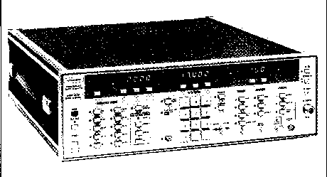
The 6600A Series (Figure 1-1) is a family of
microprocessor-based, pushbutton-controlled, GPIB-capable,
broadband signal sources that generate swept and CW
frequencies from 10 MHz to 40 GHz. This ever-expanding
family of sweepers presently consists of 29 models. These 29
models are divided into single-band and multiband sweep
generators, depending upon the number of internal bands used
for frequency-range coverage. Singleband models use one YIG
oscillator to span their range, whereas multiband models use
two or more YIGs, or a combination consisting of a YIG (or
YIGs) and a frequency down-converter.
1-4 IDENTIFICATION NUMBER
All WILTRON instruments are assigned a unique six-digit ID
number, such as "205001." The first digit of this ID (2 in
the example) represents the instrument's
year-of-manufacture; the next two (05), its manufacturing
"run;" and the last three (001), its serial number. Each
6600A Series sweep generator has two ID numbers assigned,
one for the basic frame and one for the RF deck. The ID
number for the RF deck, which provides primary
identification, is affixed to the outside of the rear panel.
The basic frame ID number appears on the inside of the rear
panel. Please use the primary (outside) serial number when
ordering parts or when corresponding with Customer Service.
1-5 OPTIONS
The following options are available for the 6600A Series
sweep generators:
• Option 1, Rack Mount. Sweep generator comes equipped with
mounting ears and chassis track slides that have a 90° tilt
capability.
• Option 2, 10 dB Step Attenuator. Sweep generator comes
supplied with a front panel or GPIB-programmable 10 dB step
attenuator. Step attenuator has a 70 dB range.
• Option 3, GPEB Interface. Sweep generator is equipped to
operate on the IEEE-488 (IEC-625) Interface Bus. With Option
3 installed, all front panel pushbuttons except POWER are
bus-programmable. Option 3 may be installed in the field.
• Option 9, Main RF Connector on Rear Panel. Sweep generator
comes supplied with an SMA female connector installed on the
rear panel rather than on the front panel.
• Option 10, Auxiliary RF Output Connector (Rear Panel).
Sweep generator comes equipped with a second RF connector
(SMA female) installed on the rear panel.
Its output power level is approximately 25 dB below the main
connector power level, and its Maximum Leveled Power
specification is derated by 1.5 dB.
Option 12, RF Output Interface, Sweep Generator to Model 661
Tracking Sweeper
Controller. Sweep generator comes supplied with a rear panel
SMA connector for supplying a 10 dB attenuated RF sample to
the Model 661 Tracking Sweeper Controller.
Option 13, Hardware Interface to HP 5342 or HP 5343A
Microwave Counter. Sweep generator comes supplied with a
rear panel BNC connector that allows the HP counter to be
used to count the marker frequency (ies).
• Option 14, Data I/O Rear Panel Connector. Sweep generator
comes supplied with a 37-pin Data I/O connector for
interfacing the Model 661 Tracking Sweeper Controller with
the IEEE-488 Interface Bus. Sweep generator must also have
Option 3 .
2 Manuals
Service and user manual
Manual type:
Service and user manual
Pages:
76
Size:
2.2 MB
Language:
english
Revision:
Manual-ID:
1-6600A/MB-OMM
Date:
Quality:
Scanned document, all readable.
Upload date:
July 31, 2014
MD5:
fd652a01-6c5b-696e-5140-176f17ae9a72
Downloads:
5251
Service and user manual
Manual type:
Service and user manual
Pages:
300
Size:
37.7 MB
Language:
english
Revision:
revised
Manual-ID:
1-6600A/MB-OMM
Date:
October 1983
Quality:
Scanned document, all readable.
Upload date:
Sept. 17, 2017
MD5:
1b1163c1-f153-0773-15e3-e4171b846294
Downloads:
8014

