
Yaesu - FT-8800R - Transceiver
Manufacturer:
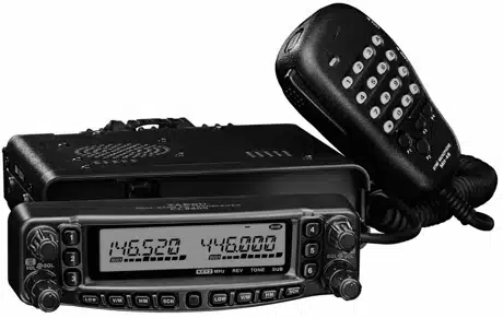
Image 1 of 1
If you have any other photos or manuals for the
Yaesu FT-8800R
you can
upload the files here.
Equipment:
FT-8800R
Date:
2003
Category:
Group:
Sub Group:
2 Manuals
User manual
Manual type:
User manual
Pages:
72
Size:
1.5 MB
Language:
english
Revision:
Manual-ID:
E H 0 1 8 M 1 0 0
Date:
Quality:
Electronic document, no scan, very well readable.
Upload date:
Dec. 26, 2010
MD5:
dc6d29e0-bd15-2acc-9ae3-2e1bb0609c27
Downloads:
1537
Last month downloads:
1
Information
Introduction ... 1
Specifications ... 2
Accessories & Options ... 3
Supplied Accessories ... 3
Optional Accessories ... 3
Installation ... 4
Preliminary Inspection ... 4
Installation Tips ... 4
Safety Information ... 5 Antenna Considerations ... 6
Mobile Installation ... 8 Transceiver Installation ... 8
Mobile Power Connections ... 9
Mobile Speakers ... 9
Base Station Installation ... 10
AC Power Supplies ... 10
Packet Radio Terminal Node Controller . 10
Front Panel Controls & Switches ... 12
LCD... 16
Rear Panel Connections ... 17
MH-48A6J Microphone ... 18
MH-42B6JS Microphone ... 19
Basic Operation ... 20
Turning the Transceiver On and Off ... 20
Adjusting the Squelch Setting ... 20
Selecting the Operating Band ... 20
Selecting the Frequency Band ... 21
Frequency Navigation ... 22
Tuning Dial ... 22
Direct Keypad Frequency Entry ... 22
Scanning ... 22
Transmission ... 23
Changing the Transmitter Power Level ... 23
Advanced Operation ... 24
Lock Feature ... 24
Keyboard Beeper ... 24
Channel Step Selection ... 24
Display Brightness ... 25
Band Linking ... 25
Audio Muting ... 26
RF Squelch ... 26 Repeater Operation ... 27 Repeater hifts ... 27
Automatic Repeater hift (ARS) ... 27
Manual Repeater hift Activation ... 28
Changing the Default Repeater hift ... 28
CTCSS/DCS Operation ... 29
CTCSS Operation ... 29
DCS Operation ... 30
Tone Search Scanning ... 31
Memory Operation ... 32
Regular Memory Channel Operation ... 32
Memory Storage ... 32
To Append an Alpha-numeric
“Tag” to a Memory ... 33
Storing Independent
Transmit Frequencies (“Odd Splits”) ... 33
Memory Recall ... 34
Memory Offset Tuning ... 34
Deleting Memories ... 34
HOME Channel Memory ... 35
Memory Bank Operation ... 36
Memory Only Mode ... 36
Hyper Memory Mode ... 37
Hyper Memory Storage ... 37
Hyper Memory Recall ... 37
Scanning ... 38
Setting the Scan-Resume Technique ... 38
VFO Scanning ... 39
Memory Scanning ... 40
How to Skip (Omit) a Channel
During Memory Scan Operation ... 40
Preferential Memory Scan ... 41
Programmable (Band Limit) Memory Scan .. 42
“Priority Channel” Scanning (Dual Watch) .. 43
Smart Search ... 44
ARTSTM: Auto Range Transponder System ... 46
Basic ARTS Setup and Operation ... 46
CW Identifier Setup ... 47
DTMF Autodialer Operation ... 48
Internet Connection Feature ... 50
Miscellaneous Settings ... 52
Time-Out Timer ... 52
Automatic Power Off ... 52
Programming the Key Assignment ... 53
FM Bandwidth & MIC Gain Control ... 54
DCS Code Inversion ... 55
Cross Band Repeater Operation ... 56
Reset Procedure ... 57
Cloning ... 58
Menu (“Set”) Mode ... 59
Service manual
Manual type:
Service manual
Pages:
55
Size:
6.2 MB
Language:
english
Revision:
Manual-ID:
Date:
Quality:
Electronic document, no scan, very well readable.
Upload date:
July 27, 2014
MD5:
d65c80de-f7cc-8e5a-7608-8278fc2f0833
Downloads:
1302
Last month downloads:
4
Information
This manual provides technical information necessary for
servicing the FT-8800R Transceiver ervicing this equipment requires expertise in handling
surface-mount chip components. Attempts by non-qualified
persons to service this equipment may result in permanent
damage not covered by the warranty, and may be illegal in
some countries.
Two PCB layout diagrams are provided for each double-sided
circuit board in the Transceiver Each side of thr board is
referred to by the type of the majority of components
installed on that side (“leaded” or “chip-only”). In most
cases one
side has only chip components, and the other has either a
mixture of both chip and leaded components (trimmers, coils,
electrolytic capacitors, ICs, etc.), or leaded components only.
Specifications
... 2
Exploded View & Miscellaneous Parts ... 3
Block
Diagram... 5
Circuit Description
... 7
Alignment
... 11
Contents
Board Unit (Schematics, Layouts & Parts)
Main Unit
...
17
Panel Unit
...
45
Panel-Sub Unit
... 51
VR-L Unit
...
53
VR-R Unit
...
54