Racal - 9087 - Generator
Manufacturer:
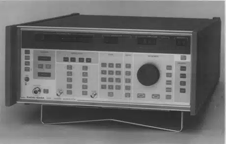
Image 1 of 1
If you have any other photos or manuals for the
Racal 9087
you can
upload the files here.
Equipment:
9087
Date:
1984
Category:
Group:
Sub Group:
Information
2.1 INTRODUCTION
2.1.1 The Racal-Dana signal generator Model 9087 is designed
primarily for the testing of communication equipment over
the frequency range from 10 kHz to 1.3 GHz. The RF output is
phase-locked to the frequency standard, the wide frequency
range being obtained by the use of a multi loop synthesizer.
The instrument is microprocessor controlled, and combines
versatility with ease-of-control.
2.2 RF TUNING
2.2.1 Tuning may be effected in one of five ways. These are:
(a) Numeric keyboard. The required frequency is set directly.
(b) Step-up and step-down keys. The displayed frequency is
changed in steps. The step size may be one of three preset
values, or an operator-set value.
(c) Spinwheel. The displayed frequency changes in steps as
the spinwheel is rotated. Again, the step size may be one of
three preset values or an operator-set value. The use of the
spinwheel, particularly with a small step size, affords all
the advantages of analog tuning while retaining the
stability of a synthesized system. A HOLD control is
provided to isolate the spinwheel to prevent accidental
changing of the frequency set.
(d) GPIB. An internal interface is fitted.
(e) Direct frequency access (DFA). The required frequency
may be set by applying suitable control signals directly to
the microprocessor data bus to a rear-panel socket. The use
of this method permits extremely rapid changes of frequency
to be made. A special interface is required. Full details
may be obtained from Racal-Dana Instruments.
2.2.2. The frequency set is displayed on a 10-digit,
dot-matrix LED display, affording 1-Hz resolution throughout
the frequency range of the instrument. The decimal point is
fixed, and leading zeros are suppressed.
2.3 FREQUENCY SWEEP
2.3.1 The 9087 incorporates a frequency-sweep facility which
permits the output frequency to be swept, in steps, between
two operator-selectable frequencies. The step size can be
selected by the operator, and four preset step rates are
available.
2.4 RF OUTPUT
2.4.1 Automatic levelling maintains the output level within
±0.4 dB for output frequencies up to 650 MHz, and within
±1.0 dB for output frequencies in the range from 650 MHz to
1.3 GHz, relative to the 50 MHz level.
2.4.2 The output-level range is from +19 dBm to -140 dBm
into 50 Ω. The level may be set by means of a numeric
keyboard, or the set value may be stepped up or down using
either the step keys or the spinwheel. The step size may be
one of three preset values, or an operator-set value.
2.5 MODULATION FACILITIES
2.5.1 Amplitude, pulse, frequency, and phase modulation
facilities are provided. Two internal-modulating
frequencies, locked to the frequency standard, are provided,
and external-modulating sources may also be used. Details of
the permissible range of modulating frequencies, and of the
modulation depths and peak deviations which can be obtained,
are to be found in Section 1 of this manual.
2.5.2 Amplitude or pulse modulation may be applied
simultaneously with frequency or phase modulation. Either or
both of the internal-modulating sources, or a combination of
internal and external sources may be used.
2.6 FR0NT-PANEL SETTING STORAGE
2.6.1 A non-volatile memory allows the storage of up to 33
(100, if the 100- location memory option is fitted) complete
sets of front-panel control settings. These may then be
recalled when required. The recalled data may be implemented
immediately, or may be displayed for checking before the
instrument output is reset. This facility allows the
contents of the store to be examined without affecting the
output of the instrument.
2.6.2 An exchange facility allows the contents of any two
store locations to be exchanged without affecting the output
of the instrument.
2.6.3 On switching off, the current front-panel control
settings are stored automatically. On switching on again,
these settings are immediately implemented. An
initialization program is also provided to set the
instrument to a known state.
2.7 ERROR INDICATIONS
2.7.1 Certain errors in the operation of the instrument will
result in the flashing of a LED-error indicator and the
generation of a service request (SRQ) via the GPIB
interface. The errors which can be detected are each given a
two-digit code, which can be displayed. The nature of the
error can then be established by reference to the pull-out
information card beneath the instrument or to Section 4 of
this manual.
2.8 DIAGNOSTIC CHECKS
2.8.1 Several points in the instrument's circuits are
monitored for possible malfunction. The detection of a fault
is indicated by the generation of an error indication. A
digit in the numeric displays will flash to indicate the
location of the fault.
2.8.2 In the event of overheating, the instrument is
switched automatically to the standby condition, with only
the frequency standard and the microprocessor system active.
2.9 SPECIAL FUNCTIONS
2.9.1 A number of special functions are available to the
operator. Details are given in Section 4 of this manual.
2.10 OUTPUT PROTECTION
2.10.1 The RF output will withstand the accidental
application of reverse-RF power at levels up to 1 W.
2.10.2 Protection against reverse powers of up to 50 W is
given by the internally mounted,
reverse-power-protection-unit option. This isolates the RF
output socket, and sounds an audible alarm, when reverse
powers are applied above the threshold level. The device
latches in the tripped state.
2.11 GPIB INTERFACE
2.11.1 An internally mounted interface to the IEEE-488-GPIB
is provided. This enables all the instrument functions,
except the line power switching and frequency standard
changeover, to be remotely controlled. An adapter to provide
compatibility with the IEC 625-1 bus is available as an
optional accessory.
2.11.2 Control via the GPIB may be exercised in one of three
ways. These are:
(a) Immediate Mode Control, in which each data byte accepted
by the 9087 from the bus is processed before the next byte
is accepted. This provides the shortest delay in completing
the resetting of the 9087's output following a data entry
made on a controller keyboard.
(b) Deferred Mode Control, in which the complete data string
is accepted from the bus and stored before processing is
commenced. The use of the bus is therefore limited to the
data transfer time, and better utilization of the bus is
possible at the cost of a small increase in the total time
taken to vary the 9087's output parameters.
(c) Learn Mode Control, in which data strings related to
particular settings of the 9087's output are generated in
the 9087 and stored in an external memory. When a data
string is fed back to the 9087 as an addressed command, the
output parameters will be set to the related values. This
provides a significant saving in time when compared with
keyboard control, and, by feeding back a succession of data
strings, the 9087 may be stepped rapidly through a number of
different output-parameter patterns. Two lengths of data
string are available, the longer controlling the full range
of output parameters and the other controlling frequency
only. The longer data string may also be used to monitor the
instrument's settings. This may be found useful when the
9087 is used in operator-interactive systems.
1 Manual
Service and user manual
Manual type:
Service and user manual
Pages:
342
Size:
48.5 MB
Language:
english
Revision:
Manual-ID:
ΤΗ 3635
Date:
Quality:
Scanned document, all readable.
Upload date:
Oct. 25, 2015
MD5:
1bad6f66-8011-d34d-f917-19a3ff0b6543
Downloads:
912