Fluke - 9000A-9900 - Interface
Manufacturer:
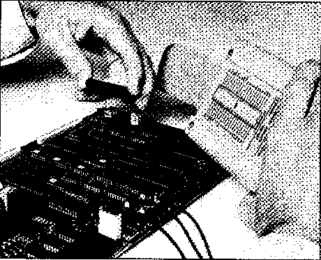
Image 1 of 2
If you have any other photos or manuals for the
Fluke 9000A-9900
you can
upload the files here.
Equipment:
9000A-9900
Date:
1981
Category:
Group:
Sub Group:
Information
The purpose of the 9000A-9900 Interface Pod, hereafter
referred to as the pod, is to interface any 9000 Series
Micro System Troubleshooter to a piece of equipment
employing a 9900 microprocessor.
The 9000 Series Micro System Troubleshooters are designed to
service printed circuit boards, instruments and systems
employing bus-oriented microprocessors. While the
architecture of the troubleshooter main frame is general in
nature and is designed to accomodate processors with up to
32 address lines and 32 data lines, the interface pod adapts
the general purpose architecture of the 9000 Series to a
specific microprocessor, or microprocessor family. The
interface pod adapts the 9000 Series to
microprocessor-specific functions such as pin layout,
status/control functions, interrupt handling, timing, size
of memory space, and size of I/O space.
1-2. DESCRIPTION OF INTERFACE POD
The pod consists of a pair of printed circuit board
assemblies, chassis-mounted within a break-resistant case. A
shielded 24-conductor cable connects the printed circuit
boards to the troubleshooter; a shielded ribbon cable and
connector provide connection to the unit under test,
hereafter referred to as the UUT.
Figure 1-1 shows the relationship of the pod to the
troubleshooter and to the UUT. Connection from the pod to
the troubleshooter is via a front-mounted 25- pin connector.
Connection to the UUT is made by plugging the ribbon cable
plug directly into the microprocessor socket. The UUT
microprocessor socket gives the troubleshooter direct access
to all system components which normally communicate with the
microprocessor.
The pod contains a 9900 microprocessor and the supporting
hardware and control software required to:
• Perform handshaking with the troubleshooter
1-1
9900
• Receive and execute commands from the troubleshooter
• Report UUT status to the troubleshooter
• Emulate the UUT microprocessor
The pod is powered by the troubleshooter, but is clocked by
the UUT clock signals. Using the UUT clock signals allows
the troubleshooter and pod to operate at the designed
operating speed of the UUT.
Logic level detection circuits are provided on each line to
the UUT. These circuits allow detection of bus shorts,
stuck-high or stuck-low conditions, and any bus drive
conflict (two or more drivers attempting to drive thesame
bus line).
Over-voltage protection circuits are also provided on each
line to the UUT. These circuits guard against pod damage
which could result from:
• Incorrectly inserting the ribbon cable plug in the UUT
microprocessor socket.
• UUT faults which place potentially damaging voltages on
the UUT microprocessor socket.
The over-voltage protection circuits guard against voltages
of+12 to -7 volts on any one pin. Multiple faults,
especially of long duration, may cause pod damage.
A power level sensing circuit constantly monitors the
voltage level of the UUT power supplies. If UUT power rises
above or drops below an acceptable level, the pod notifies
the troubleshooter of the power fail condition.
A self test socket provided on the pod enables the
troubleshooter to check pod operation. The self test socket
is a 64-pin zero-insertion force type connector. The ribbon
cable plug must be connected to the self test socket during
self test operation. The ribbon cable plug should also be
inserted into this socket when the pod is not in use to
provide protection for the plug.
1 Manual
Service and user manual
Manual type:
Service and user manual
Pages:
66
Size:
3.7 MB
Language:
english
Revision:
Manual-ID:
613745
Date:
Quality:
Scanned document, all readable.
Upload date:
Jan. 27, 2016
MD5:
6d06bb2a-8049-4c8b-8e01-6689dbd0429c
Downloads:
409