Fluke - 6071A - Generator
Manufacturer:
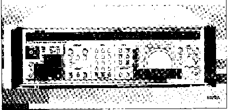
Image 1 of 1
If you have any other photos or manuals for the
Fluke 6071A
you can
upload the files here.
Equipment:
6071A
Date:
1982
Category:
Group:
Sub Group:
Information
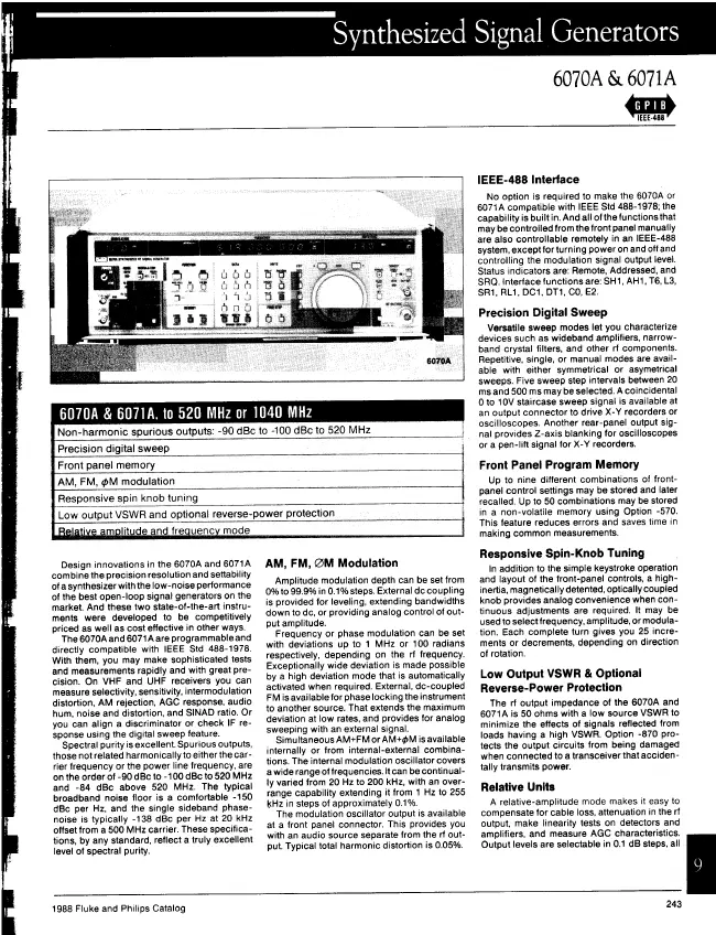
THE 6070A/6071A SYNTHESIZED RF SIGNAL GENERATOR 1-7. The
John Fluke Models 6070A and 6071A Synthesized RF Signal
Generators are designed for use in the calibration
laboratory, engineering laboratory, or manufacturing
environments. Both models offer extensive modulation
capabilities and use phase-locked loop circuitry to generate
fully synthesized signals with extremely low discrete
spurious, and phase noise. These versatile instruments are
intended for both bench and systems use. When the instrument
is used in a system, all front panel control functions
(except POWER and MOD OUT level) can be controlled via an
IEEE-488, 1978, interface.
1-8. Instrument parameters, such as output frequency and
amplitude, can be programmed to specific values or manually
adjusted using the Edit Knob (large knob near the lower
right corner of the front panel). The Edit Knob is connected
to a digital rotary encoder to provide the same continuous
manual adjustment capability that an analog tuning control
provides, but with the positive positioning of a digital
control. The rotary encoder has 25 magnetic detent
positions. The user can feel each position of the Edit Knob.
1-9. The major difference between the two models is that the
6071A has twice the output frequency of the 6070A. The
output frequency of the 6070A can be selected within 1 Hz
over a range from 200 kHz to 519.999999 Mhz (520 MHz). The
output frequency of the 6071A can be selected within 1 Hz
from 200 kHz to 520 MHz and within 2 Hz from 520 MHz to
1039.999998 MHz (1040 MHz). Both models can produce
frequencies outside of the specified ranges, but the
performance is not guaranteed.
1-10. The UNCAL annunciator will turn on to indicate that
the instrument is operating beyond specified ranges. The
synthesized RF signal is available at the front panel RF
OUTPUT connector (if the 607XA-830 Rear Panel Output Option
is installed, the RF output is available at a rear panel
Type N connector).
1-11. Internal frequency reference is a 10 MHz free air
timebase (the 607XA-130 Oven Reference Option is available
for increased accuracy and stability). This 10 MHz reference
can also be phase locked to external references of 1, 2,
2.5, 5, or 10 MHz(0.3 to 4V peak-to~peak sine or square
wave) input via a rear panel BNC connector (50 Ohm input
impedance, nominally). When an external reference is used,
the shift from internal to external is automatic. The 10 MHz
reference signal (used as the internal instrument reference)
is available as a TTL signal at a rear panel REF OUT connector.
1-12. Below 520 MHz, output level can be selected with a
resolution of 0.1 dB over the range of + 19 to -140 dBm (2 V
to 22 nV rms) into 50 Ohms. At 520 MHz or above, output
level can be selected with a resolution of 0.1 dB over the
range of+13 to-140 dBm (I Vto 22 nV rms). Selected level is
displayed on the front panel in either dBm or volts (the
instrument will convert from one to the other if the units
are changed). The internal microprocessor automatically
compensates output level for flatness and accuracy although
this automatic correction can be disabled (special function 81).
1-13. The RF output signal can be modulated in various
combinations of amplitude modulation (AM), frequency
modulation (FM), or phase modulation (0M) from internal
sources, external sources, or a combination of internal and
external sources. Table 1-1 lists all modulation
combinations and the possible modulation sources for each
combination. Amplitude modulation depth can be selected with
a resolution of 0.1 % over the range of 0% to 99.9% (see the
specifications for calibrated range). The frequency
modulation function allows the output frequency to be
deviated while the output frequency is still synthesized
unless the DCFM Mode is selected. Maximum index of
modulation that can be selected for either FM or 0M depends
upon the output frequency and the modulation frequency
selected. The internal modulation signal can be made
available at the MOD OUT connectors (front and rear panels).
An external modulation signal can be either ac or dc coupled
through parallel connectors on the rear and front panels
(MOD IN connector, 600 Ohm nominal input impedance).
External input sensitivity is such that a 1 V peak input
signal produces the calibrated modulation. The list of
specifications at the end of this section provides detailed
information about the modulation characteristics.
1-14. Up to 9 front panel setups can be stored in the
internal memory of the standard instrument, but these setups
are lost when the instrument is turned off. The 607XA-570
Non-Volatile Memory Option provides 50 memory locations.
Since this option is battery powered, front panel setups
stored in these 50 locations are not lost when the
instrument is turned off.
1-15. Three outputs are available for coordinating the
activity of associated devices: sweep analog output, penlift
output, and output invalid output. The sweep analog output
is available at the front panel SWP OUT connector. This
output steps from 0 to 10V as the frequency is swept from
the start frequency to the stop frequency. The size of the
steps depends upon the sweep width and the sweep increment
selected. The penlift output is available at a rear panel
BNC connector. This output is a TTL signal that goes high
during a sweep retrace and stays high until the next sweep
starts. The output valid signal is available at a rear panel
BNC connector. This output is a TTL signal that goes high
when output frequency, output amplitude, or modulation is
potentially unsettled.
5 Manuals
Datasheet
Manual type:
Datasheet
Pages:
4
Size:
388.6 KB
Language:
english
Revision:
Manual-ID:
Date:
Quality:
Scanned document, reading partly badly, partly not readable.
Upload date:
Jan. 28, 2016
MD5:
2c954ed5-0d8e-27cb-a138-511efb1af602
Downloads:
818
User manual
Manual type:
User manual
Pages:
30
Size:
983.5 KB
Language:
english
Revision:
Manual-ID:
Date:
Quality:
Scanned document, reading partly badly, partly not readable.
Upload date:
April 30, 2017
MD5:
da96205a-d69f-8018-af9a-769e221fb7ed
Downloads:
820
Service manual
Manual type:
Service manual
Pages:
63
Size:
1.8 MB
Language:
english
Revision:
Manual-ID:
577551
Date:
February 1981
Quality:
Scanned document, all readable.
Upload date:
Jan. 20, 2018
MD5:
b82ffb86-78b0-7ece-0a02-0fab4ee9f9bd
Downloads:
1117
Service manual
Manual type:
Service manual

Pages:
50
Size:
2.1 MB
Language:
english
Revision:
Manual-ID:
578054
Date:
January 1982
Quality:
Scanned document, all readable.
Upload date:
Jan. 20, 2018
MD5:
043c2f12-46a4-f43d-09e4-fb2ba097ec8f
Downloads:
1129
Service manual
Manual type:
Service manual
Pages:
306
Size:
12.2 MB
Language:
english
Revision:
Manual-ID:
578054
Date:
January 1982
Quality:
Scanned document, reading partly badly, partly not readable.
Upload date:
Oct. 20, 2020
MD5:
bfb61957-1051-312f-71c2-e35222984c8a
Downloads:
244