IFR - 6970 - Level Meter
Manufacturer:
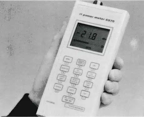
Image 1 of 1
If you have any other photos or manuals for the
IFR 6970
you can
upload the files here.
Equipment:
6970
Date:
1999
Category:
Group:
Sub Group:
Information
The 6970 Power Meter comprises a plastic case moulded in two sections. The electronic circuits are located on two multi-layer PCBs using surface mounted components.
The upper case section has the LCD PCB secured inside with the LCD visible through an aperture. The keypad assembly uses metal dome spring keys in a layered construction which is adhesively fixed to the case upper surface. Three NiCd rechargeable batteries are held in clips on the PCB.
The lower case section has the Main PCB secured inside. The SENSOR INPUT multi-pin connector, fitted to the aluminium/polycarbonate front panel, is located in a groove at the top end of the case assembly. The DC input connector is similarly located at the bottom end of the case, with a voltage regulator heat sink plate attached to it.
The Power Reference PCB is secured inside the upper section of the case, and is fixed to the LCD PCB. The power reference output N-type connector is located on the front panel of the case, next to the previously mentioned SENSOR INPUT connector.
SYSTEM DESCRIPTION
The heart of the 6970 Power Meter is an 8-bit microcontroller which provides control and timing for the unit and processes measurement data acquired through an analogue/digital converter (ADC), it also drives the liquid crystal display (LCD) and interfaces which the keypad. Program code is contained in internal ROM.
The 6970 uses a signal chopper to provide a pulsed DC voltage which is proportional to the incident RF power and thus allows AC coupled differential amplification. The tuned input amplifier is distributed between the selected sensor and the 6970 input amplifier, as shown in Fig. 1-1.
The second stage amplifier scales the signal as appropriate over four ranges before feeding the ADC, which converts the analogue signal to digital form suitable for the microcontroller to process and apply corrections.
A digital/analogue converter (DAC) is used as part of the sensor zero operation to minimize and account for system offsets when no RF signal is applied.
The internal power source comprises three rechargeable NiCd cells; two DC-DC converters are used to boost the NiCd power source to regulated +5 V and -5 V power rails required by the analogue and digital circuitry.
The optional power reference provides a 0 dBm (lmW) 50 MHz signal from a level controlled oscillator based on a dual gate FET. Thermal compensation techniques are used in the design of the oscillator such that long term drift of output power due to temperature variations are minimised.
2 Manuals
User manual
Manual type:
User manual
Pages:
48
Size:
401.3 KB
Language:
english
Revision:
Issue 12
Manual-ID:
46882-182
Date:
February 2000
Quality:
Scanned document, reading partly badly, partly not readable.
Upload date:
June 5, 2016
MD5:
bf94901c-106d-bdb2-6cb8-0216157ca4ad
Downloads:
527
Service manual
Manual type:
Service manual

Pages:
75
Size:
24.0 MB
Language:
english
Revision:
5
Manual-ID:
46882-207T
Date:
January 1999
Quality:
Scanned document, reading partly badly, partly not readable.
Upload date:
May 17, 2020
MD5:
c05cc89f-57b0-a880-cd12-f6f0ea76b945
Uploader:
Gian
Downloads:
430