Parks Electronics Laboratory - 144-1 - Converter
Manufacturer:
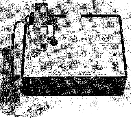
Image 1 of 1
If you have any other photos or manuals for the
Parks Electronics Laboratory 144-1
you can
upload the files here.
Equipment:
144-1
Date:
1965
Category:
Group:
Sub Group:
Information
This converter has been carefully aligned and tested for
proper gain, bandpass and noise figure. It has also been
aged for several hours so that tubes, the crystal and other
components which might fail prematurely have a chance to do
so. It is very rare that a faulty component is reported.
Nevertheless, as with all electronic equipment, some
failures are bound to occur. All parts are in warranty for 6
months. If you feel certain a part has failed then you
should write us describing the circumstances.
If it is necessary that the converter be returned to us, we
will repair it and return it to you at no charge. If you
have localized a trouble to a tube, silicon diode or
crystal, we will send you a replacement on receipt of the
defective unit. Don't attempt to troubleshoot unless you're
quite certain of your competence.
CAUTION: Do not attempt to adjust or "peak" any of the
slug-tuned coils or the piston trimmer at the input of the
converter. You can only destroy the response curve and make
the noise figure stay the same or get worse. The sensitivity
of the converter to weak signals is NOT the best where the
input or other circuits peak.
IMAGE TRAP: In the middle compartment of the converter there
is a coil and piston capacitor. This tuned circuit is set at
the image frequency of the converter. Its purpose is to
reject more fully any signal coming in at the image
frequency of the converter. The image frequency of a
converter is below the frequency to which the converter is
tuned by twice the I.F. If you have a converter with a 14
Me. I.F., the oscillator injection is at 130 Me. and the
image is at 144 minus 28 or 116 Me. If the interference from
a station near the image frequency is at 146 Me. on your
dial, the image would be at 146 minus 32 or 114 Me. If you
have a local station operating near the image frequency of
the converter, it is permissible to tune the trap a little
in an attempt to null it out more completely.
Don't change the setting much and remember about where it
was set originally. It will rarely be beneficial to adjust
the trap, so if you are not sure of yourself we suggest you
leave it alone.
I.F. CHANGE & REPAIRS: If you find that the I.F. frequency
you have chosen is not suitable because of interference from
strong TV, FM or commercial transmitters in your vicinity,
notify us of this and we will suggest remedial measures,
possibly the return of the converter for a different I.F.
The return for exchange privilege applies only to a
converter you have had in your possession for less than two
weeks before notifying us of your problem. You can always
expect a few unwanted birdies with a crystal-controlled
converter, but they should not be a problem. In many cases
of birdies, a cavity filter is the easiest solution . A very
good one was described in the February, 1965 issue of VHFER
magazine, published by our company.
1 Manual
Service and user manual
Manual type:
Service and user manual
Pages:
3
Size:
1.1 MB
Language:
english
Revision:
Manual-ID:
Date:
June 1965
Quality:
Scanned document, all readable.
Upload date:
Jan. 3, 2017
MD5:
bb5fc1fd-41f5-6de9-6341-65b699958d94
Downloads:
307