Boonton Electronic - 4200 - Digital multimeter
Manufacturer:
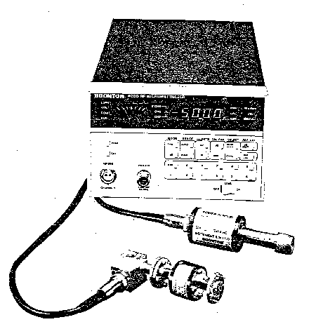
Image 1 of 2
If you have any other photos or manuals for the
Boonton Electronic 4200
you can
upload the files here.
Equipment:
4200
Date:
1987
Category:
Group:
Sub Group:
Information
The Model 4200 is a microprocessor-based solid state RF
microwattmeter. The instrument is capable of measuring RF
power levels from 1 nW (-60 dBm) to 1W (+30 dBm) for a
frequency range of 0.2 MHz to 110 GHz. The instruments
calibrated power level and frequency range is determined by
the Series 4200 sensor used with the instrument. The Series
4200 sensors are accessories and must be ordered per
application. Refer to Table 1-2 for the Series 4200 sensor
characteristics.
1-5. The Model 4200 is designed to perform the following
operations:
a. Low-power transmitter, signal generator, and oscillator
measurements.
b. SWR and return-loss measurements with directional
couplers and slotted lines.
c. Gain and insertion loss measurements.
d. RF attenuation and SWR measurements.
e. Antenna measurements.
1-6. The Model 4200 design features are as follows:
a. Wide Frequency Range. 0.2 MHz to 110 GHz. The
calibrated frequency range of the instrument is determined
by the sensor utilized. Refer to Table 1-2.
b. Wide Power Range. Depending on the selected sensor. the
instrument will measure RF power from I nW up to IW.
Temporary overloads up to 300 mW with Series 4200-4 sensors
and up to 2W with Series 4200-5 sensors will do nn permanent
harm to the instrument or the sensor.
When measuring pulsed signals, the power indications are
accurate up to 20 microwatts peak power (200 microwatts with
Se-ries 4200-5 sensors). External attenuators may be used to
extend the measurement range of the instrument.
c. Low Noise, The instrument has' been designed and
constructed to minimize noise from all sources. The sensor
cable is of a special low-noise design; vigorous flexing
causes only momentary minor deflections on the most
sensitive range of the instrument. The sensors are
insensitive to shock and vibration; even sharp tapping on
the sensor barrel causes no visible deflection on any range.
Internal signal amplification occurs at approximately 94 Hz,
thereby reducing susceptibility to 50 or 60 Hz fields. A
low-noise solid-state chopper is used.
d. LED Display. Measured power levels are displayed by a 4
digit. LED type readout with decimal points and minus sign.
Annunciators associated with the LED display indicate the
units of measurement. The resuit is a clear, unambiguous
readout that minimizes the possibility of misinterpretation.
The display is also used to show data being entered into
non-volatile memory and to display data recalled from
non-volatile memory; the display and annunciators blink on
and off during data entry and recall to indicate that
displayed values are not measured values.
e. Analog Indications. A front-panel analog meter provides
relative power' indications for peaking or nulling
applications. A dc voltage proportional to the measured
power level is available at a rear-panel connector for
application to a recorder or other external device.
f. Pushbutton Measurement Mode Selection. A choice of
measurement modes is available to the operator. Indications
in terms of power or d Bm can be selected by pressing the
appropriate front-panel key switch. A dB reference level can
be entered through the keyboard and a display mode selected
to indicate power levels in dB. relative to a dB reference
level.
g. Automatic Ranging. Autoranging under control of the
microprocessor eliminates the need for manual ranging.
Alternately, a measurement range can be retained for all
measurements, if desired, by selecting the range hold mode.
Applications of power levels that exceed the maximum or
minimum measurement capability of the instrument (or range
in the hoid mode) results in an error indication on the LED
display.
fi. Automatic Zeroing. An automatic zeroing circuit
eliminates the need for tedious, often inaccurate, manual
zeroing. With zero input to the sensor, pressing a front-
panel key switch directs the microprocessor to compute and
store zero corrections for each range, and the instrument is
thereafter corrected on each range in accordance with the
stored data. This method is considerably simpler, faster,
and more accurate than manual zeroing.
i. Automatic Sensor Compensation. Calibration factors for up
to eight sensors may be stored in the microprocessor.
Calibration data is written into non-volatile storage at the
factory for sensors ordered with the instrument; calibration
data may also be written into storage in the field. When the
sensor being used and the measurement frequency are
specified through front-panel keyboard entry, measurement
values are corrected automatically with calibration factors.
Alternately, the calibration factor in dB for a particular
sensor being used may be entered through the keyboard, and
the measurement values are then corrected a utomatically in
accordance with the correction factor. Both power and dB
values are corrected.
j. Built-in Power Reference. An accurate. 1.000 milliwatt.
50 MHz signal for instrument calibration is provided by ¿i
built-in power reference. Calibration is simpiv a matter of
connecting the sensor to the power reference, and pressing a
key: the calibration correction is computed automatically by
the microprocessor. The calibration circuit has built-in
protection against inadvertent key actuation when the sensor
is not connected to the power reference: calibration
correction is limited to approximately 7.59Í from the
original factory set value. Computed calibration corrections
that exceed this range are rejected automatically, and the
instrument returns to its previous sensitivity. If the
instrument is supplied with a 75-ohm sensor (4200-4C). an
adapter (P/N 950006) is also supplied. This adapter is used
between the power reference and the sensor to convert the
Type N power reference connector to a 75-ohm Type N. Before
calibration, a 0.17 dB CAL FACTOR should be entered to
compensate for the mismatch error that is introduced by the
75-ohm sensor. •
k. Pushbutton High/Low dB Limit Selection. High low dB
limits may be entered through the front-panel keyboard. A
front-panel annunciator indicates when measured d B levels
are outside the preset limits. Signals are also activated at
a rear-panel connector to provide remote indications of
out-of-limit measurements.
1. Soiid-state Chopper. Signal amplification in the
instrument occurs at approximately 94 Hz. Input signals from
the sensor are converted into a 94 Hz signal by a
solid-state, low-level input modulator (chopper), which
represents a distinct improvement over electromechanical
choppers. Extended service life is assured through the
elimination of contact wear, contamination, and other
problems associated with electromechanical choppers.
m. Signature Analysis Maintenance. Connection facilities to
permit signature analysis maintenance are incorporated.
Digital circuit troubles can be localized rapidly and
accurately using the signature analysis maintenance tech-
nique.-thereby reducing instrument down-time. A diagnostic
ROM (P/N 961003) is available from Boonton Electronics
Corporation for signature analysis maintenance.
1 Manual
Service and user manual
Manual type:
Service and user manual
Pages:
154
Size:
4.5 MB
Language:
english
Revision:
Manual-ID:
P/N 99 100600D
Date:
July 1987
Quality:
Scanned document, all readable.
Upload date:
Jan. 22, 2017
MD5:
d228f6ca-5ece-9758-55a0-3e58a5bc640f
Downloads:
876