BK Precision - 2125B - Oscilloscope
Manufacturer:
No picture available!
Maybe you can
upload a pic
for the
BK Precision 2125B ?
If you have any other manuals for the
BK Precision 2125B
you can
upload the files here.
.
Equipment:
2125B
Date:
2000
Category:
Group:
Sub Group:
Information
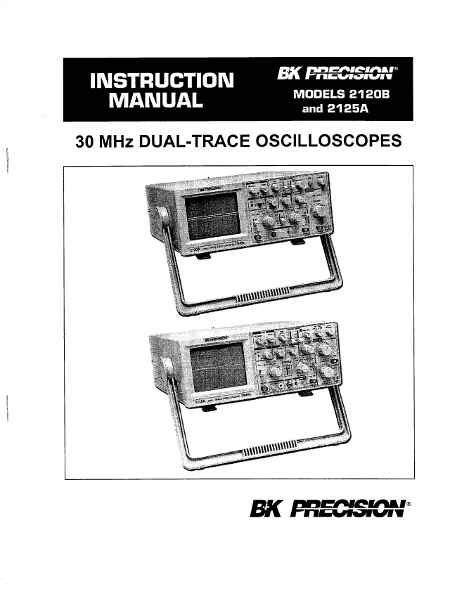
LOW COST, HIGH PERFORMANCE
B+K Precision’s entry level oscilloscopes, Models 2120B and
2125A, are economically priced to equal the competition, but
offer higher performance than the competition. For example,
most competitor’s entry level oscilloscopes have a 20 MHz
bandwidth, while B+K Precision’s Models 2120B and 2125A
offer a 30 MHz bandwidth. These oscilloscopes are built by
and backed by B+K Precision, a company that has been selling
reliable, durable, value priced test instruments for over 50
years.
CRT FEATURES
Rectangular CRT
Rectangular CRT with large 8x10 centimeter viewing area. On
Model 2125A, graticule is equipped with variable scale
illumination.
Convenience
Trace rotation electrically adjustable from front panel. 0%,
10%, 90%, and 100% markers for rise time measurements.
DUAL TRACE FEATURES
Dual Trace
Models 2120B and2125A each have two vertical input channels
for displaying two waveforms simultaneously. Selectable
single trace (either CH 1 or CH 2) or dual trace. Alternate
or chop sweep selectable at all sweep rates.
Sum and Difference Capability
Permits algebraic addition or subtraction of channel 1 and
channel 2 waveforms, displayed as a single trace. Useful for
differential voltage and distortion measurements.
HIGH FREQUENCY FEATURES
Wide Bandwidth
Conservatively-rated -3 dB bandwidth is dc to 30 MHz.
Fast Rise Time
Rise time is less than 12 ns.
Fast Sweep
Maximum sweep speed of 10 ns/div (with X10 MAG) assures high
frequencies and short-duration pulses are displayed with
high resolution.
VERTICAL FEATURES
High Sensitivity
5 mV/div sensitivity for full bandwidth. High-sen- sitivity
1 mV/div and 2 mV/div using PULL X5 gain control.
Calibrated Voltage Measurements
Accurate voltage measurements (±3%) on 10 calibrated ranges
from 5 mV/div to 5 V/ div. Vertical gain fully adjustable
between calibrated ranges.
SWEEP FEATURES
Calibrated Time Measurements
Accurate (±3%) time measurements. The main sweep has 23
calibrated ranges from 2 S/div to 0.1 (iS/div. The delayed
sweep on the Model 2125A has 23 calibrated ranges from 2
S/div to 0.1 pS/div. Sweep time is fully adjustable between
calibrated ranges.
X10 Sweep Magnification
Allows closer examination of waveforms, increases maximum
sweep rate to 10 nS/div.
DUAL TIME BASE FEATURES (Model 2125A)
Dual Sweep Generators
Main sweep gives normal waveform display, delayed sweep may
be operated at faster sweep speed to expand a portion of the
waveform.
Four Sweep Modes
Choice of main sweep only, delayed sweep only, main sweep
and delayed sweep sharing the trace (percentage of
main/delayed sweep adjustable), or X-Y.
Adjustable Start Of Delayed Sweep
DELAY TIME POSition control allows adjustment of delayed
sweep starting point.
TRIGGERING FEATURES
Two Trigger Modes
Selectable normal (triggered) or automatic sweep modes.
Triggered Sweep
Sweep remains at rest unless adequate trigger signal is
applied. Fully adjustable trigger level and (+) or (-) slope.
AUTO Sweep
Selectable AUTO sweep provides sweep without trigger input,
automatically reverts to triggered sweep operation when
adequate trigger is applied.
Five Trigger Sources
Five trigger source selections, including CH 1, CH 2,
alternate, EXT, and LINE.
Video Sync
Frame (TV V) or Line (TV H) triggering selectable for
observing composite video waveforms. TV-H position can also
be used as low frequency reject and TV-V position can be
used as high frequency reject.
Variable Holdoff
Trigger inhibit period after end of sweep adjustable.
Permits stable observation of complex pulse trains.
OTHER FEATURES
X-Y Operation
Channel 1 can be applied as horizontal deflection (X-axis)
while channel 2 provides vertical deflection (Y-axis).
Built-in Probe Adjust Square Wave
A 2 V p-p, 1 kHz square wave generator permits probe
compensation adjustment.
Component Test Function (Model 2125A)
Built-in X-Y type component tester applies fixed level ac
signal to components for display of signature on CRT.
Channel 2 (Y) Output (Model 2125A)
A buffered 50Q output of the channel 2 signal is available
at the rear panel for driving a frequency counter or other
instruments. The output is 50 mV/div (nominal) into 50£2.
Z-Axis Input (Model 2125A)
Rear panel Z-Axis input allows intensity modulation.
Supplied With Two Probes
1 Manual
User manual
Manual type:
User manual
Pages:
24
Size:
1.7 MB
Language:
english
Revision:
Manual-ID:
Date:
January 2000
Quality:
Scanned document, all readable.
Upload date:
Jan. 24, 2017
MD5:
21e60e26-d0de-2772-d60e-c1d5360c683f
Downloads:
639