Fluke - 752A - Other
Manufacturer:
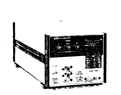
Image 1 of 1
If you have any other photos or manuals for the
Fluke 752A
you can
upload the files here.
Equipment:
752A
Date:
1984
Category:
Group:
Sub Group:
Information
The John Fluke Model 752A is a self-calibrating, precision
dc voltage divider with two ranges of division: 10:1 and
100:1. In addition to the two divider ranges, the 752A
incorporates switching modes used in the cardinal point
calibration of dc voltage calibrators. The points provided
on the 752A are 0.1V, IV, 10V, 100V, and 1000V. When the
752A is combined with a dc voltage calibrator, a 10V
reference standard, and a null detector, the 752A switches
the equipment to standardize the dc voltage calibrator
without having to physically change the leads.
1-3. The 752A is self-calibrated before each use. This
procedure requires a stable source and a null detector. The
752A is a ratio device only, and does not have to be
included in a calibration cycle that is traceable to an
external standard.
1 -4. The front panel MODE switch selects between self-
calibration and normal operation. In the Self-Calibration
mode, the voltage divider resistors are compared using an
external null detector to an internal, self-calibrating
bridge to precisely set their overall value, and hence, the
division ration of the 752A. The three push-to-tum CALIBRATE
controls adjust the 10:1 divider, 100:1 divider, and the
self-calibration bridge. The CALIBRATE switch selects the
divider to be calibrated and interchanges the two resistors
in the self-calibration bridge to check that they are of
equal value. If not, the BALANCE control adjusts one of
these resistors by a small amount to make both
selfcalibration bridge resistors equal in value.
1-5. In normal operation, the MODE switch settings
correspond to the cardinal calibration points of a dc
voltage calibration system. The MODE switch now
interconnects the external equipment in one of three ways
(refer to Figure 2-3):
1. The voltage divider of the 752A is connected between the
reference standard and the null detector as shown in Figures
2-3a and 2-3b.
2. The voltage divider is out of the circuit and the
reference standard is compared directly with the UUT (unit
under test) as shown in Figure 2-3c.
3. The voltage divider is connected between the UUT and the
null detector as shown in Figures 2-3d and 2-3 e.
1 Manual
Service and user manual
Manual type:
Service and user manual
Pages:
65
Size:
5.1 MB
Language:
english
Revision:
Manual-ID:
645069
Date:
April 1984
Quality:
Scanned document, all readable.
Upload date:
Feb. 4, 2017
MD5:
ca66e184-dd5d-df9a-b3c5-3680e7362572
Downloads:
571