Brüel & Kjær - 2626 - Amplifier
Manufacturer:
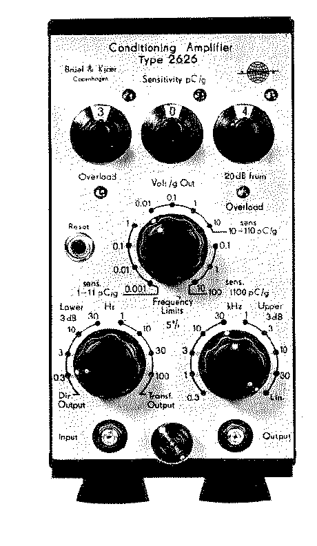
Image 1 of 1
If you have any other photos or manuals for the
Brüel & Kjær 2626
you can
upload the files here.
Equipment:
2626
Date:
Category:
Group:
Sub Group:
Information
When measuring vibration by means of an accelerometer, it is
necessary to incorporate a preamplifier between it and the
measuring amplifier. The preamplifier is introduced in the
measuring circuit for two reasons:
1. to transform the high output impedance of the
accelerometer to a lower value and
2. to amplify the relatively weak output signal from the
accelerometer.
The signal from the piezoelectric accelerometer appears as a
voltage across a capacitive impedance. As the capacitive
output impedance of the accelerometer is very high, the
associated amplifier must be of a special design having a
high input impedance. This is necessary in order to avoid
loading of the accelerometer and thereby obtaining decreased
sensitivity and limitation at the low end of the frequency
range.
The combination of a charge amplifier and a piezoelectric
accelerometer gives a sensitivity which is independent of
cable length within very wide limits. This feature makes a
charge amplifier especially attractive in vibration systems
where different cables are used. The Conditioning Amplifier
Type 2626 may be used with cable lengths up to several
thousand meters.
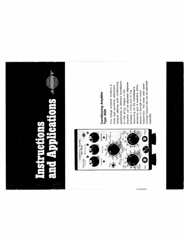
Another advantage the 2626 Amplifier offers is the wide
conditioning possibilities to different transducers and
measuring requirements. It features a 3 digit sensitivity
adjustment network which enables the amplifier sensitivity
to be adjusted to the particular transducer used. The
network is calibrated in pC/g. Output of the amplifier can
be adjusted stepwise between 1 mV/g and 10V/g, depending on
the transducer sensitivity. A maximum sensitivity of 1 V/pC
is available. The output signal is available either directly
coupled or through a transformer (switchable) for floating
output.
Stepwise adjustable HP and LP filters are incorporated, by
which the frequency limits can be adjusted independent of
sensitivity. The filter scales give the 5% as well as 3 dB
frequency limits. The lowest frequency limit for the
amplifier is 0.3 Hz which makes it quite suitable for
measurement of impulses.
Two neon indicators are connected to the output, one for
overload and the other for underload which lights when the
signal level is at least 1 V peak. On account of quick
recovery time after overload, the amplifier is also suitable
for use in a servo-loop in exciter systems.
2 Manuals
User manual
Manual type:
User manual
Pages:
17
Size:
848.7 KB
Language:
english
Revision:
Manual-ID:
Date:
Quality:
Scanned document, all readable.
Upload date:
May 26, 2017
MD5:
c39452e8-40bc-df7b-718f-8ac52c2c9896
Downloads:
762
Datasheet
Manual type:
Datasheet

Pages:
8
Size:
509.0 KB
Language:
english
Revision:
Manual-ID:
Date:
Quality:
Scanned document, all readable.
Upload date:
June 1, 2017
MD5:
39d3d502-6fca-5b94-09bc-61362af8e1c9
Downloads:
1567