Kikusui Electronics Corporation - TOS5052 - Test Set
Manufacturer:
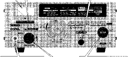
Image 1 of 1
If you have any other photos or manuals for the
Kikusui Electronics Corporation TOS5052
you can
upload the files here.
Equipment:
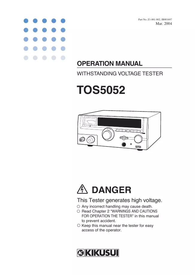
TOS5052
Date:
2004
Category:
Group:
Sub Group:
Information
TOS5052 Overview
The TOS5052 is a 5 kV AC/100 mA withstanding voltage tester
which functions output voltage presetting, output frequency
selection (50/60 Hz), and the rise time control function
which can control the rise time up to the preset voltage.
Features
1. For test complying with major industrial standards
Each of the TOS5052 allows you to conduct withstanding
voltage tests (dielectric strength tests) of electrical and
electronic devices and components, complying with major
industrial standards including UL, CSA, BS, and JIS
(Japanese Industrial Standards) and Electrical Equipment
Control Ordinances of Japan.
2. Rise-time control function
The UL's type certification test and IEC standard require
that the test voltage be raised gradually up to the preset
level. The rise-time control function of the TOS5052 can
automatically raise the test voltage to the prespecified level.
3. Improved test voltage waveform quality
(a) Generates a test voltage waveform which is independent
of the waveform of the AC line voltage.
(b) Generates a 50 or 60 Hz low-distortion test voltage
waveform.
4. Stabilized test voltage
(a) Allows the test voltage to be preset.
(b) Generates a test voltage that is independent of the AC
line voltage.
(c) Assures a voltage regulation of 9% or less (maximum
rated load to no load)
5. High voltage output
(a) Provided with a large-capacity high-voltage power supply
which supplies the maximum rated voltage of 5 kV/100 mA (500
VA) (for 30-minute test time) or
2.5 times higher than that of our preceding models.
(b) Generates a momentary short circuit current of 200 mA
(for a test voltage is 1 kV and UPPER current of 100 mA)
which is required in an IEC standard. (Cannot generate this
current continuously because the output is automatically
shut off by an over current protection mechanism.)
6. Rational layouts of keys and switches
The keys have a slant-plane for easy viewing and convenient
operation. The switch for test voltage range select and the
control for test voltage adjustment are installed
concentrically, allowing you to operate them conveniently
with two concentric knobs. For adjustment of
pass/fail-judgment limit current setting and that of timer
setting, respective increment/decrement keys are provided.
These keys and switches, together with the large display
easy to view, are laid out rationally and will assist you to
conduct your tests accurately and efficiently.
7. A large color display
The TOS5052 has a large color VACUUM FLUORESCENT DISPLAY. It
is a wide viewing angle type of display with high intensity,
and clearly indicates information in clearly readable large
letters and in color annunciators. The indicated information
includes test conditions, instrument status, readback
current, result of pass/fail judgement, etc., assisting you
to conduct your tests accurately and efficiently.
8. Analog/digital voltmeters
The TOS5052 is furnished with an analog voltmeter (±5%
full-scale) and a digital voltmeter (±1.5% full-scale). The
analog voltmeter serves as an output indicator and the
digital voltmeter as a high-precision output voltmeter for
accurate and prompt testing.
(Neither analog nor digital voltmeters can be used to
measure any external voltages that are present outside the
TOS5052. An attempt to apply an external voltage to their
output terminal would cause fatal damage to the TOS5052.)
9. A digital ammeter
The TOS5052 has a digital ammeter to measure the current
that flows through the DUT (device under test).
10. A window comparator for pass/fail judgement
The TOS5052 has a window comparator for pass/fail judgment
with reference to both upper (U) and lower (L) criteria
(cutoff current). The comparator generates a FAIL signal
when the measured current that flows through the DUT is
greater than the preset upper limit criterion or even when
it is less than the preset lower limit criterion. The L FAIL
detection function contributes to improve the test
reliability by detecting open-circuiting or imperfect
contacting of the test leadwires. Separately for each of U
type and L type of fail, the TOS5052 indicates a fail
annunciator message on its display and delivers a fail event
signal, allowing you to immediately find out the type of the
fail.
You can preset the upper limit and lower limit currents
(cutoff currents) mutually independently of each other
(0.1mA to 110mA, AC).
11. A digital timer
The timer allows you to preset the period during which the
test voltage is to be applied to the DUT. The preset range
is 0.3 to 999 seconds. When the timer function is ON, the
preset period is decremented and the timer indicates the
remaining period; when it is OFF, time is incremented and
the timer indicates the elapsed period.
12. Remote control provision
The tester has provisions for remote start/stop control
operation. That is, it has a 5-pin DIN connector (for the
optional Remote Control Box or High Voltage Test Probe) on
its front panel and a 14-pin Amphenol connector on its rear
panel. The remote control function, together with the status
signal function, will help you conduct efficient automatic
labor-saving tests.
1 Manual
User manual
Manual type:
User manual
Pages:
102
Size:
8.3 MB
Language:
english
Revision:
Manual-ID:
Z1-001-802, IB001697
Date:
March 2004
Quality:
Scanned document, all readable.
Upload date:
Sept. 2, 2017
MD5:
aa12c9bc-c4c3-3d19-d713-11d4ece2bf5a
Downloads:
315